When you click on links to various merchants on this site and make a purchase, this can result in this site earning a commission. Affiliate programs and affiliations include, but are not limited to, the eBay Partner Network.
I suspect they did this so that if the fan siezed or was unable to turn due to debris, that the resistors would get very hot, and trip the thermo switch. It's better than the wires turning red hot and causing a fire.
I suspect they did this so that if the fan siezed or was unable to turn due to debris, that the resistors would get very hot, and trip the thermo switch. It's better than the wires turning red hot and causing a fire.
What I don't understand is, what the hell are the fan wires doing inside the cabin anyway? The fans are outside, the relay is outside, and on the later models the resistors are outside where they logically belong. On my car, there's a harness that just pokes through into the battery area with 4 wires, just to go through the resistors and back into the cabin again!
I suspect they did this so that if the fan siezed or was unable to turn due to debris, that the resistors would get very hot, and trip the thermo switch. It's better than the wires turning red hot and causing a fire.
If the fans were to seize, wouldn't the current draw spike and blow a fuse?
I used a 944 cooling fan motor for a project several years ago (a machine that autonomously plays fetch with a dog) and I measured ~7A draw in steady state for 1 motor on our lab supply, IIRC. It kept blowing up transistors we were using to PWM it. On startup it was definitely over 20A.
If the fans were to seize, wouldn't the current draw spike and blow a fuse?
Most likely not. I've held the blades stationary when they tried to come on and it didn't blow a fuse. Don't try this at home kiddies! Those things hurt if they hit you.
The pics you show of them being jumped to themselves is not correct. Someone changed it or hooked them up wrong long before you.
As an example coffee pots use the same type of thermal switch. Once the heating plate reaches the specified temperature, the switch "pops" and cuts power. Once the plate cools off the switch "pops" again and allows the plate to heat up. Rinse and repeat. So if you have a drip coffee maker at home, and hear it "pop" from time to time, you're hearing the thermal switch working. Super cheap way to control temperature.
For those to work correctly in your car, power has to come from the fuse panel, though the thermal switch, to the resistor, and then to the fan.
Maybe it bypasses the resistor's when the resistor plate gets to hot? Why would they want cut the power to the fan's and risk the car overheating?
A better setup would have the fan's run in series for low speed and parallel for high speed eliminating the resistors. Could be done with a few relays.
Maybe it bypasses the resistor's when the resistor plate gets to hot? Why would they want cut the power to the fan's and risk the car overheating?
A better setup would have the fan's run in series for low speed and parallel for high speed eliminating the resistors. Could be done with a few relays.
I'm pretty sure the stock set up bypasses the resistors when the fans run on high speed. So if the resistors are cut out from getting too hot, the coolant temp will rise and the fans will start running on high speed (unless the key is out, in which case the engine can't overheat anyway).
This makes me think that what they had in mind was not so much the fans getting stuck, but rather the low speed mode running for too long if the engine is running too hot.
As you know the resistors are there for low speed fan operation. High speed just feeds the fans the full 12 volts.
In theory, cutting the power to the low speed resistors would be ok, since the engine would then run hotter and eventually kick in the high speed mode.
The thermal switches are there to act as a self resetting fuse. If a short were to happen on the low voltage side, it would draw more and more current through the resistor and heat it up way beyond normal levels. It would take a lot to burn up one of those resistors. One of those burning up and catching fire in your cabin would not be good. Under normal operations the resistors will generate a specific amount of heat and not trip the thermal switch. So maybe the switches are set to trip say 20-30 degrees above normal. ?? Just a guess.
Doubtful the fuse would pop in time if a short were to happen on the low power side of the resistor. That may or may not happen before wires start smoking.
Power and current is a very funky thing. I've seen overloaded 110 volt outlets catch fire, melt down and never trip the breaker or blow a fuse. Also have seen voltage regulators on motorcycles short out and draw so much current they melt wiring harnesses and never blow fuses.
interesting, thanks for the input everyone. Just an update after several hours of rewiring and testing:
I build a new harness for the resistors and both run in high speed mode, but I'm still only able to get one to operate on low speed and I believe I've found the issue. Of the 4 wires that go to the resistors, 2 are grounds and 2 are switched 12v. Both the grounds are good, but only one of the hot wires is actually getting power. Where does the power to the resistors come from?
Edit: I see from the wiring diagram the power to the resistors comes from the cooling fan Relay. Does each low speed circuit have its own contact? In other words, is it possible that one low speed fan works but one doesnt and the source of the lack of power to one of the resistors is the relay? If I'm looking at the diagram right, the relay has 4 individual contacts in it, which I presume are hi/low respectively, 2 per fan?
I saw another thread about a similar issue and decided to copy/paste the relevant info. I am now pretty certain I have a bad contact inside my fan relay.
4. Connect the jumper between M1 30 to M1, the drivers fan should run at high speed. If the fan does not run, check for voltage in the connector at the fan motor, if you have voltage but the fan does not run, replace the fan motor.
5. Check the passenger fan by connecting the jumper between M2 30 and M2, the passenger fan should run at high speed. If not, the same drill.
6. Next connect the jumper between M1 30 and V1, the drivers fan should run at low speed. If not the resistor or wiring is bad. Check for voltage at the radiator fan connector and then check the resistance across the resistor.
7. Next connect the jumper between M2 30 and V2, the passenger fan should run at low speed. If it does not run, check the wiring and resistor.
FML. I am not getting power to the relay at position 30M2, so it appears the problem is in the fuse panel. If that is the case, how then can both fans run in high speed?
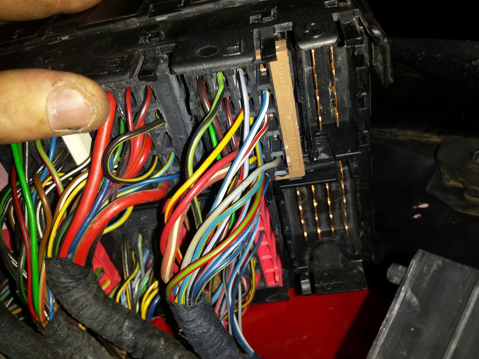
Which connector feeds the cooling fan relay? I've pulled the two most logical and pin 30M1 still has power so I must not have gotten the right ones. Everything looks normal under the relay board but i reeeeally need to figure out why I dont have power at 30M2 since this is my daily driver.
Problem is solved, I had to perform surgery under the fuse box but my fans operate properly now and I feel better with fresh, properly done wiring under the fuse panel and under my dash. I'll post some pictures of the repairs later, for now I'm just satisfied everything is working.
Also, for what its worth; I DID bypass the thermal switches and the car did fine on a 90 minute hard run tonight, so we'll see if my car catches fire or not in the next few weeks
 08-09-2016, 06:17 PM