When you click on links to various merchants on this site and make a purchase, this can result in this site earning a commission. Affiliate programs and affiliations include, but are not limited to, the eBay Partner Network.
I have been lazily installing MS3 on my 88' 944 Turbo since late last year and wanted to share with you all my experience. As of now the car is running and tuned, in my opinion, pretty darn well.
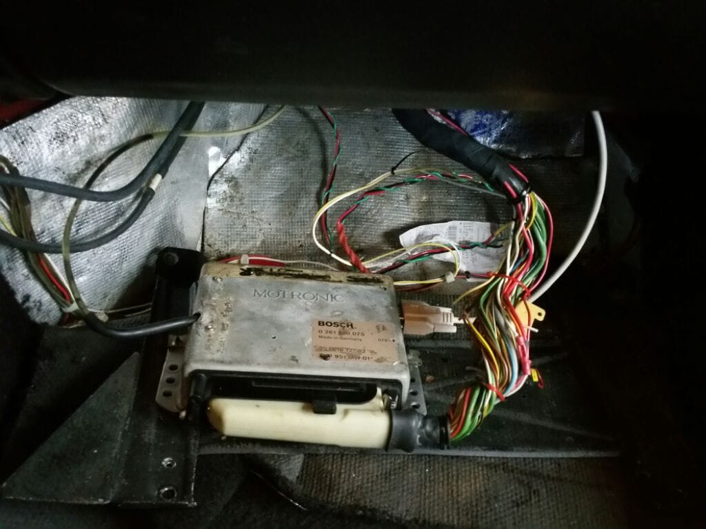
So to start, I will describe my overall setup and why I went with MS3 in the first place. I bought my car in may of last year, my 2nd turbo and my 3rd 944, and it was running the factory DME with 951MAXX chips installed. The car was also fairly modified, which is what I was after in the first place. Here is a short list of things that are done to the car.
My Car!
1. Garrett T04E 57 Trim Turbo
2. 3 inch down pipe/exhaust to rear axle with resonator, 4" axle back
3. 55 lb/hr injectors, 3BAR FPR
4. Tial 40mm
5. LR Flywheel, KEP Pressure plate, Clutchmasters 6 puck
6. AC Delete
7. AEM UEGO
There is a bunch of interior/Exterior/Suspension stuff to but these are the main items that were affecting the way the car ran. These items coupled with chips that may not have been burned for this exact setup are the reason I decided to go MS. The car had cold start problems, high vibration at idle, around town drivability issues due to aggressive drive train modifications. I am happy to say since installing MS, all of these issues are marginally better if not completely fixed.
When deciding which version of MS to use I was heavily influenced by some friends who also run MS in their cars plus the fact that I am a DIY guy and now on my 3rd 944 I decided I wanted to go as deep as I could with this car. What better way to do this than building a MS3 V3.0 board from scratch, so that is the way I went.
Main Board Build
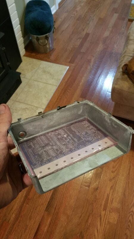
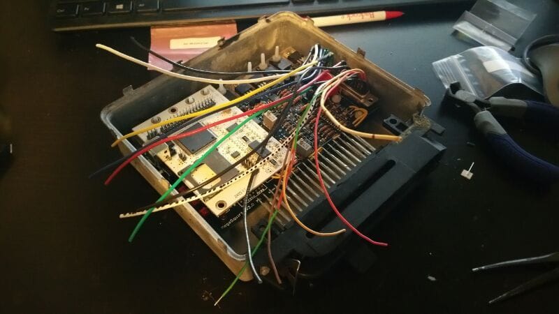
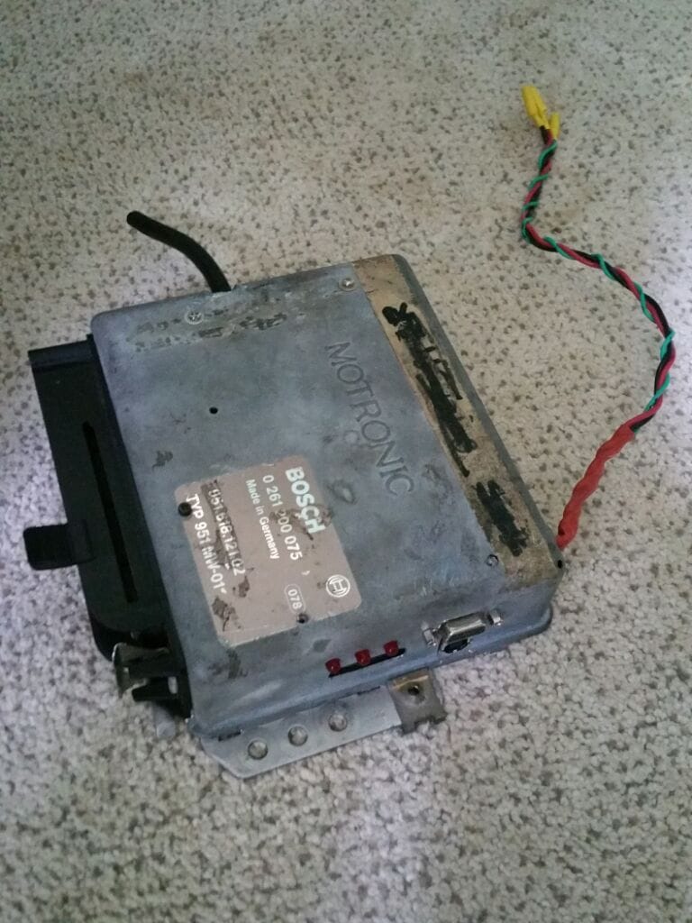
I ordered the MS3 DIY kit from DIYAutoTune.com and as soon as I opened the box, I noticed that the main board was just slightly smaller than the DME enclosure.
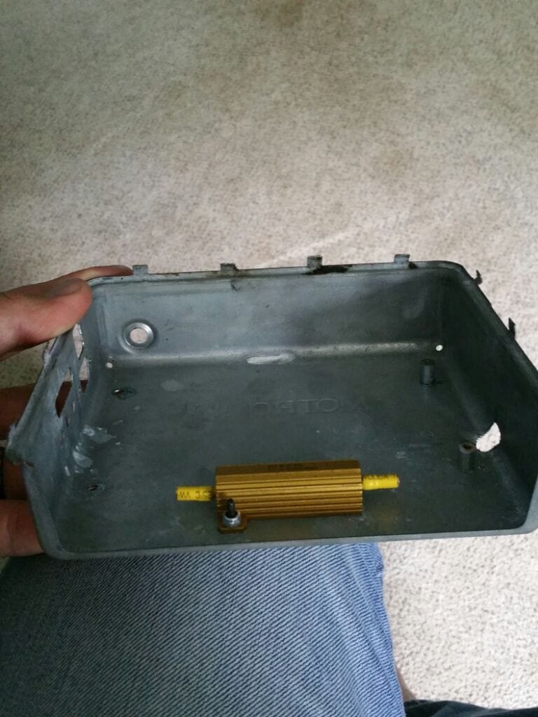
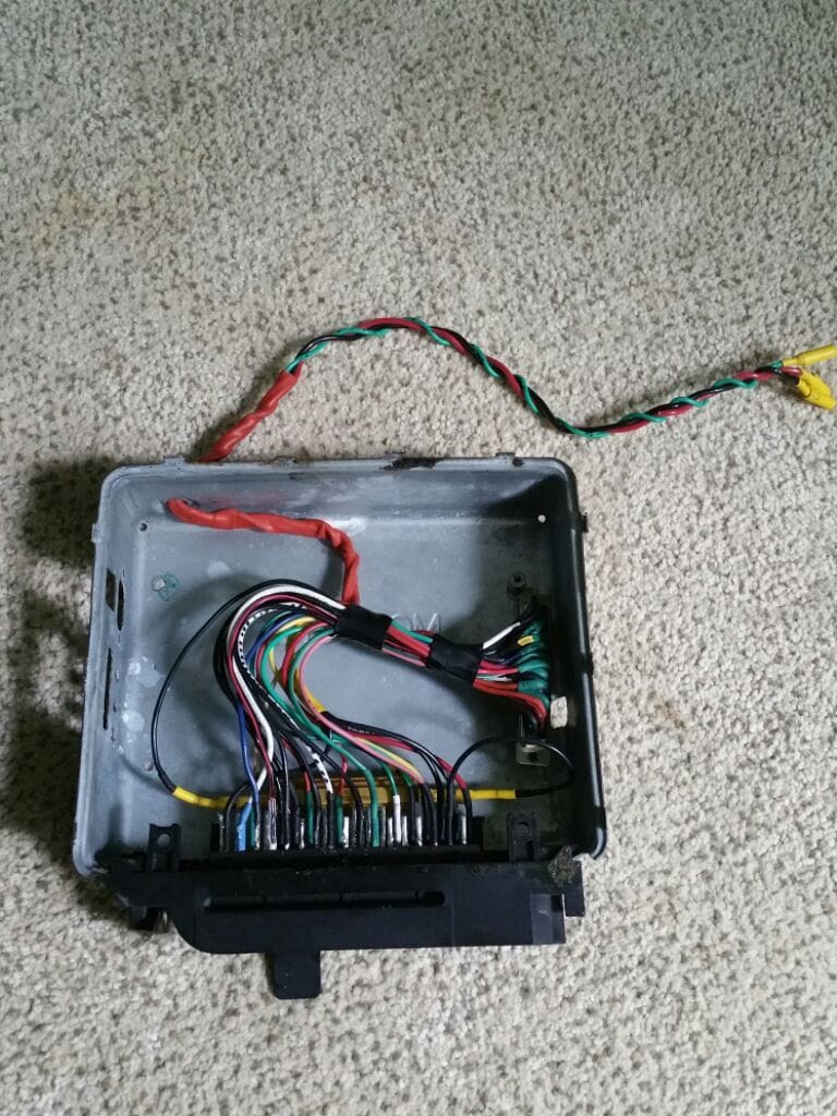
I had an extra dead DME laying around from my old car so I decided I was going to cannibalize it so that I could splice directly into the factory wiring and, if I ever decided to, I could always turn it back to stock.
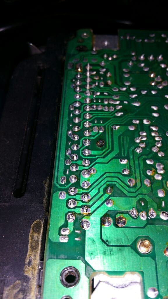
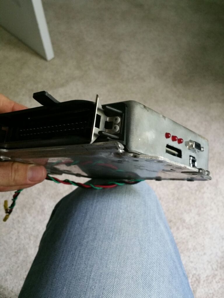
All I had to do was de-solder the 35 pin connector from the DME board, modify the pins and mount everything inside the enclosure...once the board was built.
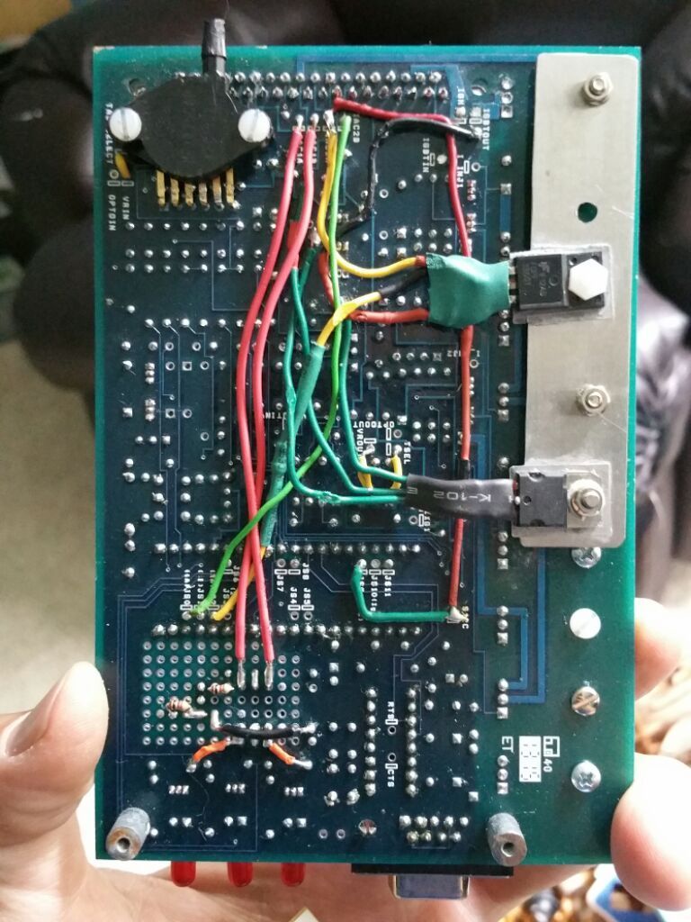
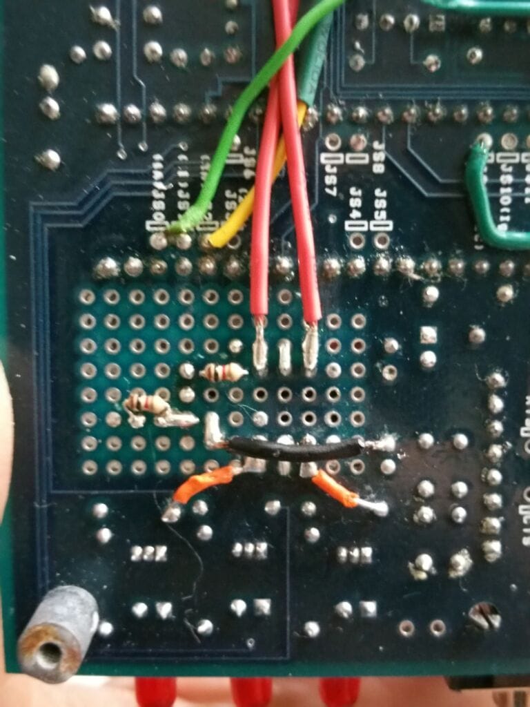
solder joints on bottom of DME board
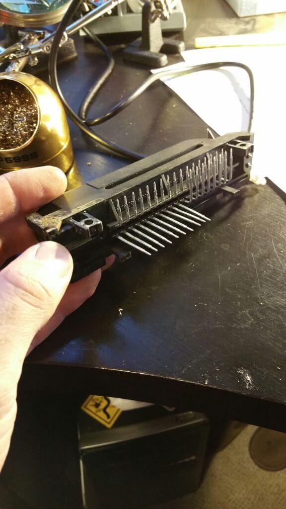
Bending pins straight for solder points of patch harness
The board build was pretty straight forward, I just followed the build manual located HERE. This build was for MS2 V3.0 and I later found out that THIS MANUAL is better to follow. In the end it really doesnt matter other than you need to test everything. The manual I used had me build circuits in order and then test them, whereas the newer manual suggested building everything and testing it all after the fact.
This is the order I did things, per the mega manual. Let me know if you all have questions on these procedures but they are in the manual.
1. Power circuit
2. Serial Communication
3. VR Circuit
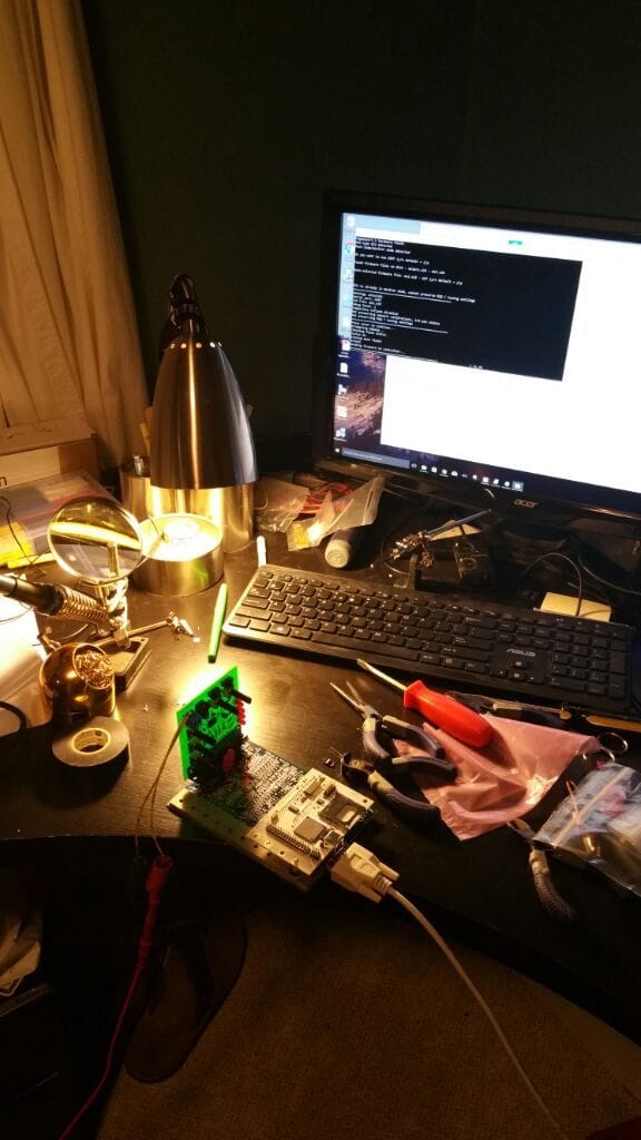
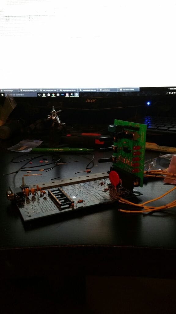
Testing Serial Comms with with power circuit installed.
Testing Power Circuit with Stim
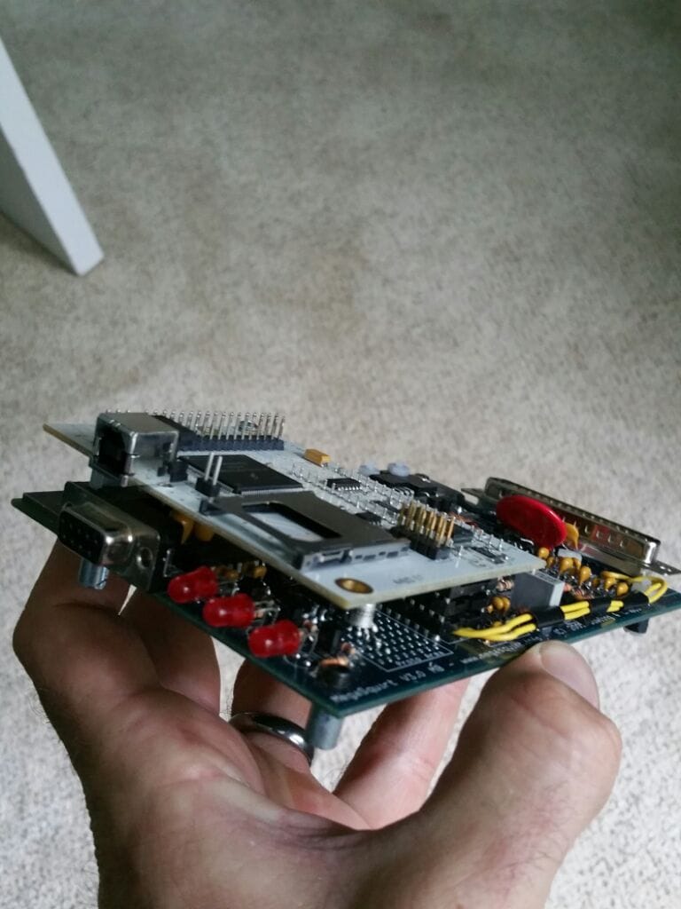
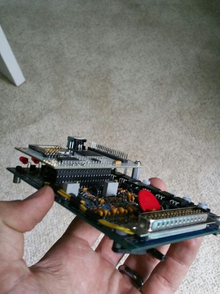
At the end of the day, the build is really straightforward. You get a board that is labeled for every resistor, capacitor, diode, and transisor needed as well as individual bags that correspond to the numbers on the board. If you install the diodes correctly, and anything else directional which are also marked on the board, you cannot mess it up. It's a very fun soldering project but I would recommend practicing on a smaller project if you have never done it before.
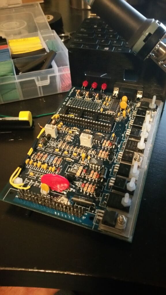
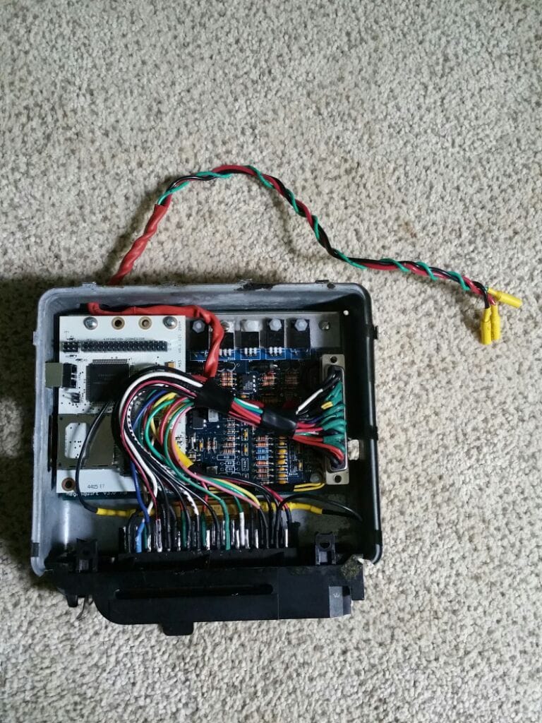
Fully Built board!
full board mocked in enclosure with 35 pin connector
Patch Harness Build
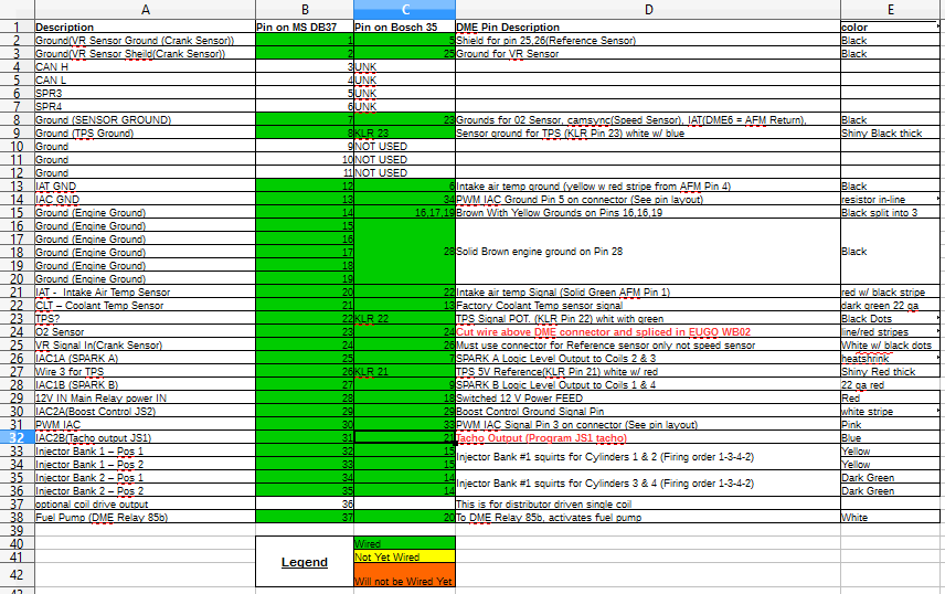
So now that the board was mocked up I needed to build a short patch harness to connect the DME inputs and outputs to the DB37. Most of this was fairly straighforward, see the Excel sheet laid out below for how I hooked everything up.
EDIT: Below is an updated patch harness, this one has the correct Tacho wiring (I had it hooked to the wrong pin and thats why it didnt work, should have been DME pin 21) Updated patch harness wiring
Originally I planned on using the factory coil and dizzy but could not get it to work properly. I had always planned to upgrade to wasted spark so I decided to wire the coils, build a bracket and build a custom wire set. More on this in a subsequent post. The reason I note it here is the patch harness is wired for it and it may throw some people off when looking at it. Also, I had to use 3 pins from the KLR for throttle position and therefore had to tap that harness...this is the only part of the install that is outside of the DME box. I dont really like it but there was no way around it. I also cut the wire for the narrow band 02 sensor and spliced in my AEM WB02 (the white wire 0-5V) and used the signal wire for the AC compressor (DME pin 29) to run the PWM circuit for my Electronic boost control which I have not set up yet.
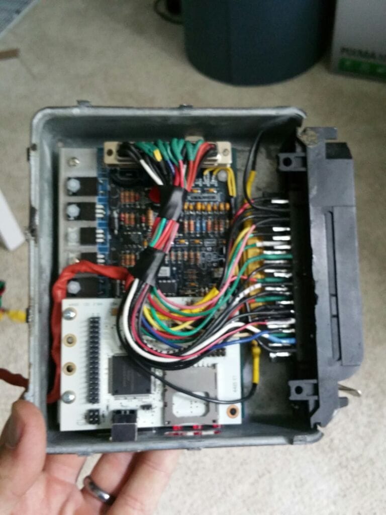
So it is worth noting here that I made a bit of a mistake with the way I connected the patch haness to the board. I used the DB37 female pin connector that came with the MS3 kit but did not have a proper pin header to mount on the PCB. I did however have 2.54 mm spacer pins for micro-controllers and such. So I used those and soldered two rows of these pins. Unfortunately the pins have a rectangular profile while the female DB37 was looking for round pins. I did not find out this was a problem until I tried to start/drive the car. I was getting bad readings from my sensors and it affected everything. Thus I had to buy a straight DB37 pin header like this one, which is from walmart of all places. It worked like a charm.
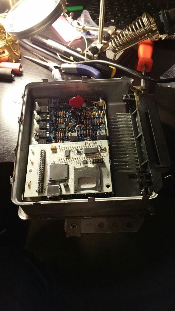
patch harness laid in ECU
Ill put a finished picture in here of the full enclosure with the patch harness attached to the DME connector next time I pull it out of the car.
Below is my MS setup and Tune for those interested. My setup is also listed above for those considering using my tune as a base. Please use my tune files with caution, the map is solid but it wont be perfect for your setup. Use this as a baseline to start with and tune the car yourself. MSExtra.com has lots of good stuff on this.
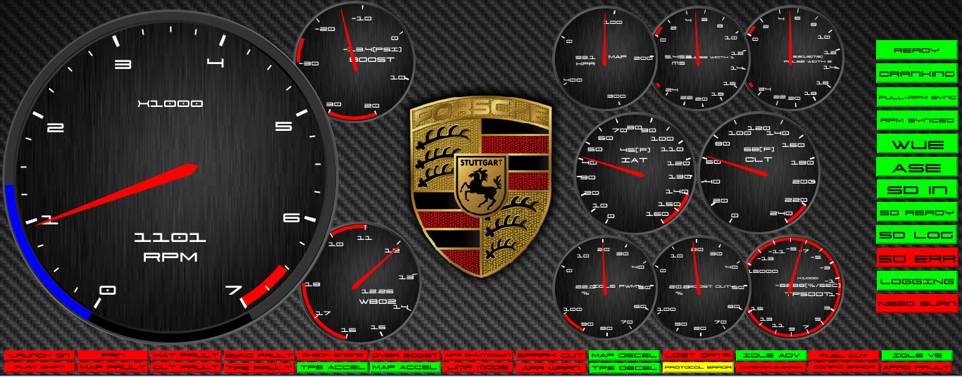
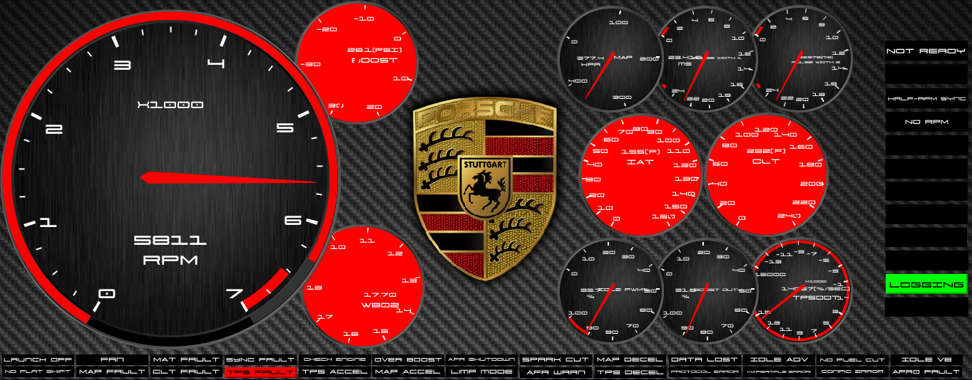
I also included my .dash file because I like the dash I designed and maybe you do too. Let me know what you think. If you want to use it youll have to rename the file extension to .dash because rennlist deems this as an invalid file format.
A couple shots of my custom dash in demo mode
Last edited by SpeedFrK; 08-23-2016 at 10:49 PM.
Reason: Adding Content
I spy with my little eye NC lic plates... you in fort mill/rock hill area?
- Can't wait to see the rest of the how-to, thinking of eventually going MS
How strange, my family is from Fort mill and I grew up there but I live in Greenville SC now. Honestly these photos are from the PO's ad when I bought the car from the NODA area.
MS is pretty awesome but not for the faint of heart, you'll see as my thread grows I learned alot the hard way. It's also one of those things that is never really completely done if your doing it yourself without unlimited access to a dyno but this is why I do it. My car is as much a project as it is a car to drive/race/show. I love the stuff.
Following this.... curious to see your MSQ, I'm throwing a MS3X in my 951. Also curious to see your cam pickup, I noticed you have 4 injector channels called out.
Following this.... curious to see your MSQ, I'm throwing a MS3X in my 951. Also curious to see your cam pickup, I noticed you have 4 injector channels called out.
I am actually running banked injection. You'll see on my spreadsheet that on the MS side there are 4 injector pins but I soldered bank1 together and same for bank 2. The reason was that the DME runs banked from the factory and I didn't have the outputs on the 35 pin to do outputs. I do however have plans for running semi-sequential but have not executed. I wanted to get the car running better than I ever could with the DME and banked got me there. I really like the Clewitt engineering cam sensor they make and may add that on and run it through the speed sensor input. This might require running ms3x card which I do not have room for in the factory enclosure...no biggie though I can throw something on the makerbot..
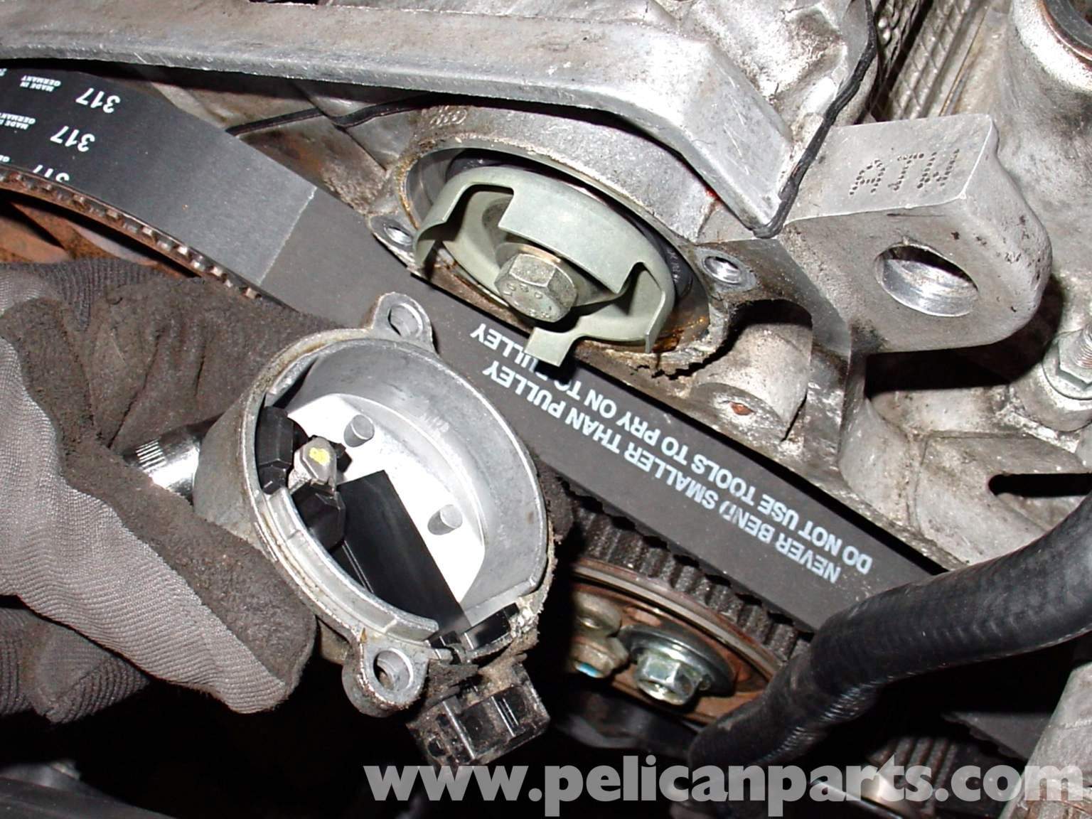
I have a budget cam sensor idea I'm going to mock up on my 951 when I get the chance. Basically an Audi cam sensor, which looks like this:
...but with 1 window in the vane wheel instead of 4. I have a couple, they're abundant in junkyards on late 90s+ Audis and VWs. The bolt that retains it is M8 just like the cam cog retainer on our 944 cam towers so it will center. With a basic thick washer, the vane wheel would sit proud of the cam cover by the right amount, and then it's just a matter of bolting the sensor housing on over it, I think they're 2-off M6 holes that would need to be created. The output is a clean digital signal, perfect for a cam input.
+1 all day. This is great stuff. Is it a 2 wire VR or Hall effect type? So I understand you would use the VW vane wheel and just mod it or make a new one?
It's a hall effect type sensor (3 pins, with symbols on the connector for power/signal/ground), plug and play with no shielded wire or analog-to-digital processing required. Yeah the vane wheel will bolt where the distributor rotor was, and the sensor housing bolts to the cam gear cover, on top of it. You can kind of see the actual sensor in the picture, the vane moves past it, and the ECU is sent an "on" of "off" signal. There are setup instructions in section 6.9.9 of the MS3 hardware manual, it's super straightforward.
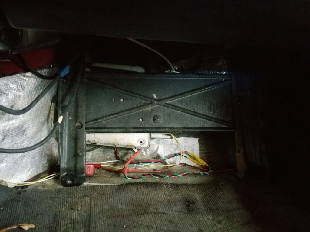
Only thing I still need to post is engine bay images and take a video of her idling and getting into boost to complete the story, which I will take tomorrow. Hope you guys enjoy this, it has been a fun project for me...it never ends. Let me know if you have questions on how I did any of this.

 07-10-2016 | 12:45 PM