Notices
924/931/944/951/968 Forum Porsche 924, 924S, 931, 944, 944S, 944S2, 951, and 968 discussion, how-to guides, and technical help. (1976-1995)
Sponsored by:
Sponsored by:

Instrument Cluster Wiring Diagram

Thread Tools
 
Search this Thread
 
Old 09-02-2014, 09:30 AM
  #1  
sdisselhorst
Track Day
Thread Starter
 
sdisselhorst's Avatar
 
Join Date: Aug 2014
Posts: 21
Likes: 0
Received 0 Likes on 0 Posts
Default Instrument Cluster Wiring Diagram

I am attempting to bench test my gauges, but I do not have the wiring diagram to know the pinouts of the connectors. Does anyone have this? I have decided if I can just bench test my gauges, it would save a lot of time in my troubleshooting.

I am pretty sure I can recreate the signals needed to simulate driving, but I need to know which pins are what signal.

-Thanks

Maybe I could make a "gauge tester" unit and make it available, or at least its design, on these forums.
Old 09-02-2014, 10:14 AM
  #2  
Van
Rennlist Member
 
Van's Avatar
 
Join Date: Oct 2002
Location: Hyde Park, NY
Posts: 12,008
Received 92 Likes on 62 Posts
Default

http://www.cannell.co.uk/Manuals_Original.htm
Old 09-02-2014, 11:44 AM
  #3  
sdisselhorst
Track Day
Thread Starter
 
sdisselhorst's Avatar
 
Join Date: Aug 2014
Posts: 21
Likes: 0
Received 0 Likes on 0 Posts
Default

None of the links there seem to be real. Can't download the PDFs.
Old 09-02-2014, 11:53 AM
  #4  
Van
Rennlist Member
 
Van's Avatar
 
Join Date: Oct 2002
Location: Hyde Park, NY
Posts: 12,008
Received 92 Likes on 62 Posts
Default

Oh, bummer. They used to work. Do a web search (or a rennlist search).
Old 09-02-2014, 03:27 PM
  #5  
cliffjumper
Advanced
 
cliffjumper's Avatar
 
Join Date: Apr 2014
Location: Gisborne, New Zealand
Posts: 50
Likes: 0
Received 1 Like on 1 Post
Default

Which dash style do you have?
Old 09-02-2014, 03:33 PM
  #6  
sdisselhorst
Track Day
Thread Starter
 
sdisselhorst's Avatar
 
Join Date: Aug 2014
Posts: 21
Likes: 0
Received 0 Likes on 0 Posts
Default


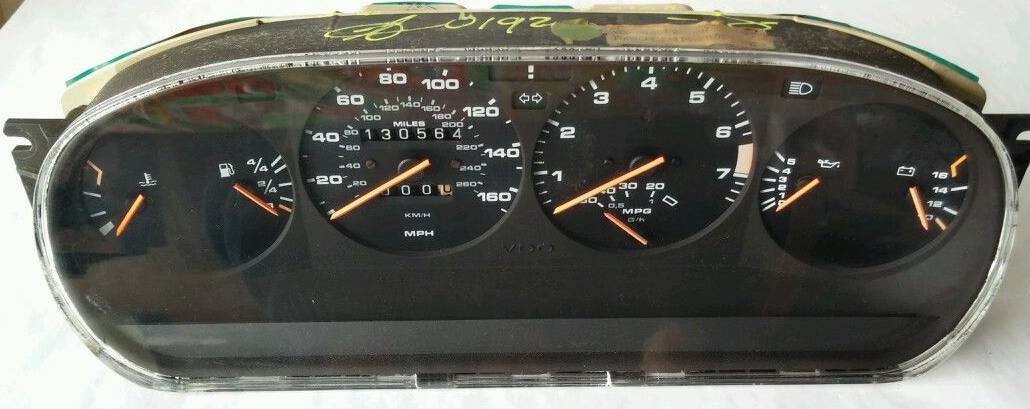
1986 944 NA, should see a pic.
Old 09-02-2014, 04:54 PM
  #7  
931guru
Rennlist Member
 
931guru's Avatar
 
Join Date: Feb 2007
Posts: 2,708
Received 317 Likes on 259 Posts
Default

951

Last edited by 931guru; 09-03-2014 at 11:14 AM.
Old 09-03-2014, 12:01 AM
  #8  
Tom M'Guinn

Rennlist Member
 
Tom M'Guinn's Avatar
 
Join Date: Jan 2002
Location: Just CA Now :)
Posts: 12,567
Received 534 Likes on 287 Posts
Default

Originally Posted by sdisselhorst

I am pretty sure I can recreate the signals needed to simulate driving, but I need to know which pins are what signal.

-Thanks

Maybe I could make a "gauge tester" unit and make it available, or at least its design, on these forums.
I just went to Best Buy and bought their 944 Instrument Cluster Signal Simulator. Video below... Happy to help if I can....

https://www.youtube.com/watch?v=u_Tv...ature=youtu.be
Old 09-03-2014, 10:48 AM
  #9  
sdisselhorst
Track Day
Thread Starter
 
sdisselhorst's Avatar
 
Join Date: Aug 2014
Posts: 21
Likes: 0
Received 0 Likes on 0 Posts
Default

Wow. Exactly what I need. Can I borrow it?
Old 09-03-2014, 07:50 PM
  #10  
FRporscheman
RL Community Team
Rennlist Member
 
FRporscheman's Avatar
 
Join Date: Jun 2004
Location: San Francisco Area
Posts: 11,014
Received 20 Likes on 15 Posts
Default

Originally Posted by Tom M'Guinn
I just went to Best Buy and bought their 944 Instrument Cluster Signal Simulator. Video below... Happy to help if I can....

https://www.youtube.com/watch?v=u_Tv...ature=youtu.be
Did you make that yourself? I'd love to build one!
Old 09-03-2014, 09:46 PM
  #11  
944Ross
Rennlist Member
 
944Ross's Avatar
 
Join Date: Dec 2008
Location: NM (ABQ)
Posts: 2,238
Likes: 0
Received 7 Likes on 7 Posts
Default

I believe that's a variable frequency square-wave generator?
Old 09-04-2014, 12:04 AM
  #12  
Tom M'Guinn

Rennlist Member
 
Tom M'Guinn's Avatar
 
Join Date: Jan 2002
Location: Just CA Now :)
Posts: 12,567
Received 534 Likes on 287 Posts
Default

Originally Posted by 944Ross
I believe that's a variable frequency square-wave generator?
You could call it that -- it is an arduino project I've been making to drive the instrument cluster on the bench. Since the first video, I redid the code so that the speedo increases linearly with the ****.


The speedometer and the tachometer work on ground pulses -- the faster the signal is pulsed to ground, the higher the reading. For details on the speedometer, see my calibrator project here:

http://members.rennlist.com/tom86951...r%20Page1.html

The arduino reads the pot on the **** and creates it's own pulse to drive the speedometer. The tachometer works the same way, although the pulse rates are obviously different.

The other gauges are essentially volt meters. See more info in these threads:

https://rennlist.com/forums/944-turb...achometer.html

https://rennlist.com/forums/944-turb...e-control.html

https://rennlist.com/forums/944-turb...e-control.html
Old 09-04-2014, 03:46 AM
  #13  
FRporscheman
RL Community Team
Rennlist Member
 
FRporscheman's Avatar
 
Join Date: Jun 2004
Location: San Francisco Area
Posts: 11,014
Received 20 Likes on 15 Posts
Default

That's a great project, I think I'll make one myself!
Old 09-04-2014, 06:01 AM
  #14  
dorschmix
5th Gear
 
dorschmix's Avatar
 
Join Date: Sep 2014
Posts: 5
Likes: 0
Received 0 Likes on 0 Posts
Default

None of the links there seem to be real.
Old 09-04-2014, 10:04 AM
  #15  
sdisselhorst
Track Day
Thread Starter
 
sdisselhorst's Avatar
 
Join Date: Aug 2014
Posts: 21
Likes: 0
Received 0 Likes on 0 Posts
Default

So, the speedometer doesn't need to be driven with anything stronger than the Arduino output pin? I figured it would need a pulsed 12v signal going through a transistor or FET. Thanks for the info!


Quick Reply: Instrument Cluster Wiring Diagram


All times are GMT -3. The time now is 11:25 PM.