When you click on links to various merchants on this site and make a purchase, this can result in this site earning a commission. Affiliate programs and affiliations include, but are not limited to, the eBay Partner Network.
Wow, again, a thorough recap. Thanks, although a bit depressing, especially considering that I'm coming up on the 1 year anniversery of the car being off the road.
I recently bought a used DME off of eBay. It didn't work either.
What happens when I turn the key to the "on" position is that there is a 12+ volt signal that travels through the DME to the KLR to female pin #9 on the KLR harness. If I remove the DME (or the DME relay) the 12+volts signal drops to 6+ volts. If I then also remove relay G2 the signal drops to zero. During cranking, this signal should then alternate between 12+ and zero in a square wave pulse as the DME converts the analog signal from the reference sensor to digital signal to the coil. This doesn't happen. The signal stays steady at 12+ volts. I have retested the imput from both the reference and speed sensors--they're still good. They both seem to produce close to 12 volts during cranking. Since there is no max voltage (min is 2.5v for the speed and 2v for the reference) stated in the official manual I've always assumed that this 12v value was okay. I have also moved the sensor block up and down at various times to vary the sensors' output. This had no effect on the no start, although it did reduce the output voltage. The pivot sleeve was in good shape and the movement of the mounting block seemed normal.
I have tried to start the car with the G2 relay removed (that kills the dash instruments) but that had no effect--the 12+ signal still failed to alternate. I also unhooked the coil low tension wires (terminals #1 and #15) and the 12+ signal is still there! That's right, even with no power going into the DME on wire #1 from the coil, there still was that 12+ signal present at terminal #9 on the KLR harness. I also unhooked the T21 connector (for the tach) and that also made no difference.
So...either the DME is not alternating the current for the coil to fire for some internal reason (despite being rebuilt and retested by Specialized ECU Repair and an exact same fail by another DME), or the reference sensor is not triggering the DME to create a digital signal (despite passing every possible test, despite being replaced with a new unit, despite replacing the wiring harness that connects the speed and reference sensors to the DME), or there is some unknown reason that prevents the DME from alternating this signal.
As always, I am open to suggestions....
Possibilities: could there be something about the speedometer sensor on the transaxel that would prevent the car from starting? something that would prevent the car from being driven without the odometer recording mileage? Could there be something with the airbags that would prevent the car from starting if the airbag system wasn't working correctly?
I can't get the oil level light to go out.
Also, I've ordered and received the "Y" shaped vacuum connectors for some of the intake vacuum lines. They don't seem to flow any air when I suck or blow (no jokes, please) through them. Is this normal??
Thanks again to everyone that has responded and to everyone that follows this tale of woe. I'll keep posting until the car is running or towed away.
What do you mean when you say "the sensors produce 12 volts"?
Being Hall effect sensors, I'd expect their pulses to be in the milivolt range.
Have you been able to confirm that both sensors are gapped correctly? The speed sensor is 0.8mm from the steel ring gear teeth and the steel set screw on the flywheel is at the right height (I forget what it is right now, but think it's about 4.5mm)?
It seems to me, based on the number of DMEs you've tried and your test results, you have some issue with the sensors. Either your test procedure is incorrect or, as Specs suggests, the signal from one or both sensors isn't distinct enough for the DME to pick it up.
P.s. I would expect that the idiot lights, including oil level, won't go out until the engine is running.
Air bag, or lack thereof, will not affect starting; same goes for the speedo sensor.
All vacuum lines and the intake should be unrestricted if you in plug them. Some of the lines go to objects with a diaphragm - like the BOV, heater valve, etc. - these should be "sealed".
Van is correct. Far as I know the speed sensor on the tranny should make no difference. Mine was unplugged a while after I did my clutch - no issues. Oil level warning goes off when my car is a bit low and has been parked on a slope. No impacts on starting.
Looking at my schematics - there are two leads exiting from DME pin 21. One goest to KLR pin 9. The other goes to DME connection plug T1 at pin2. The connection at T1 (pin 2) is the signal which goes to your tachometer. Something in your tachometer or the wiring to it may be feeding the steady DC voltage you are seeing.
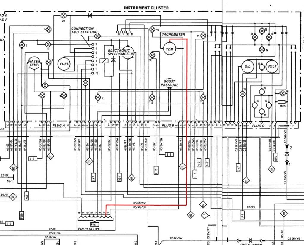
Here are screen shots from the 87 turbo wiring diagrams with circuit paths in question highlighted in red
Instrument Panel
DME/KLR Wiring
Note that any problem with the tach holds potential of directly inject DC voltage to your DME / KLR via the 8 pin plug which connects to your instrument panel.
Lamp 19 in the instrument panel wiring diagram is the "Central Warning Light"; Lamp 11 is the "High Beam" light. I don't have the identification sheet for MY87 wiring diagrams which tells where this 8 pin "Pin Plug DME" / "Wire Conn DME" is located . The MY88 wiring diagrams identify this plug as Connector T1 and show it's location to be in the passenger footwell. Your's is likely in the passenger footwell. Mine was.
Last edited by specsalot; 11-11-2014 at 10:10 AM.
Reason: improve clarity
What happens when I turn the key to the "on" position is that there is a 12+ volt signal that travels through the DME to the KLR to female pin #9 on the KLR harness. If I remove the DME (or the DME relay) the 12+volts signal drops to 6+ volts. If I then also remove relay G2 the signal drops to zero. During cranking, this signal should then alternate between 12+ and zero in a square wave pulse as the DME converts the analog signal from the reference sensor to digital signal to the coil. This doesn't happen. The signal stays steady at 12+ volts. I have retested the imput from both the reference and speed sensors--they're still good. They both seem to produce close to 12 volts during cranking. Since there is no max voltage (min is 2.5v for the speed and 2v for the reference) stated in the official manual I've always assumed that this 12v value was okay. I have also moved the sensor block up and down at various times to vary the sensors' output. This had no effect on the no start, although it did reduce the output voltage. The pivot sleeve was in good shape and the movement of the mounting block seemed normal.
I have tried to start the car with the G2 relay removed (that kills the dash instruments) but that had no effect--the 12+ signal still failed to alternate. I also unhooked the coil low tension wires (terminals #1 and #15) and the 12+ signal is still there! That's right, even with no power going into the DME on wire #1 from the coil, there still was that 12+ signal present at terminal #9 on the KLR harness. I also unhooked the T21 connector (for the tach) and that also made no difference.
...
Perry
Best I can see (looking at paper copies of the MY88 schematics in front of me) there are 3 connectors which hold the potential of delivering power to you computers:
T21 - The 14 pin connector (driver side under hood @ firewall) powers both computers and engine sensors. - Normally plugged into receiving socket.
T1 - The 8 pin connector (passenger footwell) which delivers sensor outputs to the instrument panel. - Normally plugged into receiving socket.
T26 - Knock Control Diagnosis Plug (passenger footwell) - Normally nothing is plugged into this connectors socket.
With the "Key On" the ignition switch feeds B+ to terminal 15 of the coil. This same circuit out of the key switch also feeds:
1. Coordinates G18/N48 - Instrument cluster (may not be only feed to cluster - haven't fully run this down)
2. Coordinates C4/M48 - Hazard Light Switch and Terminal 86 of G2 relay. G2 relay supplies B+ to brake lights and cruise control unit
3. Coordinates F38/N48 - Alarm Control Unit (your car may not have one, but theres a plug connector for it).
4. Coordinates F100/N48 - Air Bag Control Unit
5. Coordinate E58 - Terminal 86 of Relay G13 (horn relay) [identified at N49 but not given coordinate labeling]
Your quote describing symptoms (highlighted in red above) holds the key to figuring this situation out. In the last part when you say "T21 connector (for the tachometer)" are you referring to the 8 pin connector in the passenger's footwell? The answer is right in front of us (somewhere <g>). I just don't see it yet. Review the wiring diagrams I sent you a link to.
If I'm understanding things correctly - unplugging T1 and T21 should take all power off your computers. Relay G2 draws B+ power for the holding coil off the key switch. If there was an electrical problem with G2, it could be feeding power out of Terminal 86 with the key off. Something smells fishy about Relay G2 from your symptom descriptions above. Note the MY87 schematics do not label the instrument connector as T1 explicitly but it appears equivalent to what is labeled T1 in MY88 schematics.
Thanks for your input. Paul, again, thanks for the huge amount of work on your part.
I spent some time down in the garage tonight. Almost nothing new. I do have some clarifications.
1) Van, when I say that the sensors produce 12 volts, I mean that the sine wave generated by the speed sensor during cranking has an amplitude of 12 volts--+6 volts above the x-axis and -6 volts below. The reference sensor produces a spike that has a similar amplitude. I have also repeatedly checked the gap for the sensors. It is where it is supposed to be.
2) Specs, I switched the T1 and T21 connections in my descriptions. The T1 connection is the one in the passenger's footwell and connects the DME to the dash instruments. The T21 connection is the fourteen pole connector by the brake booster in the engine bay. I have disconneted the T1 connection for some of my testing. The T21 connection is fine--no corrosion or broken wires, continuity with the DME relay, etc. I have removed the G2 relay for some of the testing--no change.
Okay, the new part. Here's what I think is preventing my car from starting. During my testing tonight, I got the same +12 volts between the KLR harness pin #9 and ground when I turned the key on. This is with the DME connected and the DME relay working to energize the DME. Cranking should generate a alternating square tooth signal but doesn't. Just for grins, I hooked up the oscilloscope to KLR harness pin #16. Remember, KLR harness pin #9 is the input of the ignition signal from DME pin #21, and KLR harness pin #16 is the output for the ignition signal. KLR harnes pin #16 ALSO has 12+ volts! I then disconnected the DME and put the ohm meter on KLR harness pins #16 and #9 and got no continuity. BOTH #9 and #16 have 12+ volts with the key on. What that means (I think) is that 12+ is going through the DME from DME pins #18 and #35 to the KLR indicating that there is a defect within the DME. From the wiring diagram pin #16 on the KLR connects to pin #32 on the DME. If I disconnect the DME or the DME relay I get no voltage at either pin when I turn the key on. I performed all these tests with the T1 (dashboard instruments) connection unhooked. I also performed this test with the "new" DME I bought from eBay--exact same result.
This weekend, I will work on moving the speed and reference sensors away from the flywheel in an attempt to lower their output voltage to see if that will trigger DME to fire the coil.
Specs, I have stared at that particular page from the wiring diagram for the last 8 months to no gain.
Your description helps illuminate - Good work. It would be interesting to note if the +12 volt signal DME to KLR goes to zero if you unplug the crank reference and/or speed reference sensors.
I was just looking up the test script from the FSM... It looks like your total peak-to-peak voltage has to be greater than 2.5v (which it sounds like you have) for the speed sensor and 2.5v from baseline to peak for the reference sensor. However, I think you've called it a square wave pulse - but it should be a true sine wave.
The signal from the DME to the KRL is a square wave (pin 9 and ground).
Also, resistance of the sensors should be between 0.6 to 1.6 k-ohm (measured between DME pins 8 and 27 for speed, and 25 and 26 for ref). There should be no shorts between pins 8 and 5 (speed), and pins 26 and 5 (ref) (more than 1 M-ohm).
Have you tried another set of speed and reference sensors?
I'm not at all sure that the steady (mostly) 12 VDC you are seeing on the DME/KLR link (DME 21 to KLR 9) is originating within the DME. It could be, but there is also a chance it is the result of an external short in the harness. I also don't understand why unplugging the DME OR the DME relay drops the link voltage to 6 VDC. Disconnecting the DME would isolate a number of ground points. I believe these symptoms lie at the heart of the issues you are experiencing.
You've been assured by Specialized that you have a working DME/KLR. You've also substituted a spare DME that is supposed to be good with the same lack of results. In my view this strongly suggests that the issue is not with the electronics per se, but rather with the interface (i.e. DME harness).
We know from the schematics that voltages are fed to the computers (DME/KLR) through a number of points (this may not be a complete list).
T21 Pin 7 - From Ignition Switch - Informs DME that engine is being started.
T21 Pin 5 - Completes the circuit in the DME Relay which operates the fuel pump. Connects to DME pin 4 which should be providing a ground for the circuit.
T21 Pin 3 - Supplies B+ to DME 35 and 18 when first stage of DME Relay is energized
T21 Pin 2 - Supplies B+ to common side of fuel injectors and timing valve and the KLR Pin 6 when the first stage of the DME relay closes energizing B+ to Terminal 87.
T21 Pin 1 - Supplies return path from Ignition Coil Terminal 1. DME grounds and isolates coil circuit to fire the spark plugs.
T21 Pin 13 - Supplies voltage to DME to indicate that the AC compressor is operating
One of these voltages sources may be shorting across to the DME/KLR input link (DME 21 - KLR 9). One way to test for this would be to unplug all your engine sensors / devices and computers and T21. Then continuity test DME plug pin 21 against T21 points for continuity. Then do the same for KLR plug pin 9. I think this may reveal a potential short if one exists from traditional voltage supply points in the harness. Keep working it, I think you are very close. If this doesn't identify a problem there are other things to look at. One step at a time. Low hanging fruit first.
The challenge with staring at anything for 8 months is that at some point you stop seeing. That is what these forums are all about - fresh eyes, fresh perspectives, and shared experiences.
I disconnected both the speed and reference sensors from the DME harness at their connectors at the back of the intake manifold. There is still 12+ volts at pins #9 and #16 on the KLR harness with the key on. I will disconnect the idle air valve tonight and run the same test.
Actually, we're assuming that having 12+VDC at KLR harness pins #9 and #16 is abnormal. Maybe, it's supposed to be that way.
Could you test your car for this output? Anyone else with a 951 willing to do this??
I used the oscilloscope, but a regular VOM will also work. With the KLR disconnected, measure DC volts between ground and KLR harness pins #9 and #16. Cranking the engine should alternate the voltage between 12 and 0, although most VOM won't be able to react quickly enough to accurately show the changing voltage.
One of the problems I've had doing this testing is that I am not always able to interpret results/measurements that I get in any meaningful way because I'm not sure what I'm supposed to get.
A good case in point is the 6+ volts I get at pin #9 on the KLR harness with the DME disconnected. Is that normal or is it a symptom that could lead us to the solution of this no start? I have no idea. Or how about the 73 ohms between the coil #15 terminal and ground. Is that normal? I wouldn't think so, but maybe it is.
All I know is that following the official Porsche diagnosis manual confirms the diagnosis that the DME itself is bad. Test point 15--if there is no square wave signal between KLR harness pin #9 and ground during cranking they say to replace the DME.
Perry
Good Points - I will try to test my car after I reinstall the intake. Between now and then, here is what my FSM lists for computer pin outs.
For those following along. Here is a link to a better looking wiring diagram for MY87. I color coded lines based on function / related circuits. The dropbox place holder doesn't look very clear, but if you down load the file it's pretty legible. Its a 2 MB file 3316 x 1661 pixel jpeg.
 11-11-2014, 01:31 AM