When you click on links to various merchants on this site and make a purchase, this can result in this site earning a commission. Affiliate programs and affiliations include, but are not limited to, the eBay Partner Network.
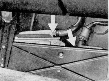
Decided the night wouldn't be complete without a surface dive into my passenger footwell. I wish my foot well was a squared away as this picture. Mine has a nest of wires - lots of extra length - not sure why that is. I'm pretty sure I have a MY90 DME harness in my car. Perhaps they are longer? If I had to do my harness work over again (hopefully never), I wish I had just popped coin for a new Porsche DME harness. Instead I spent ~ $400 on repair kits. Ugggggg. What I have is solid now so I better not write more about it. Already blew up the car budget for the year.
Tested KLR Connector Pin 9 voltage two times under different conditions with interesting results.
Test 1
Battery connected with Key switch in Run
DME computer connected
KLR computer disconnected
KLR Connector Pin 9 = ~0.043 VDC
Your car more or less matches Test 2 results I got on my car. But your Test 1 results are way off.
I think perhaps your DME computer connector may not be fully engaged when you have the DME plugged in. I've found that it's easy to have the connector partially engaged but not fully seated. You need to rotate the connector about 30 or 40 DEG above the datum of the DME. Enter the DME connector tab into the slot. Apply some slight pressure to the left as you rotate the connector into position. It must click in to under the retaining bar.
Look at both connectors and make sure all connectors are in place in the plug. DME has contacts in all plug holes. KLR has a few holes with no connectors. These are shown as white rectangles in the diagrams in my last post.
I've never run into a situation where I've powered my DME up only partially connected. But I always double check to be sure the DME plug is latched under the retainer. More than once it looked like it was there, but was not. You should hear a metallic "click" when it snaps into place.
Needless to say, but if you ever need one of my kidneys or someone killed (or both), I'm your guy.
That's very interesting. I'm betting that if you remove the G2 relay, that ~6 volts will drop to zero. The G2 relay powers the instrument panel.
Obviously, your Test 1 shows that there shouldn't be 12 volts at the KLR harness pin #9. With my car as soon as I turn the key to the run position with the DME in place and powered up, I get 12 volts there.
The $64 question is WHY?
What did I do to this car during the clutch job that caused this?
This weekend I will see if I can exactly determine which 12+ input into the DME is causing the DME to send out the 12 volts to pin #9. I STILL think that the DME is bad--either as a symptom of some other problem, or as the root cause of the no start (and my current unhappiness).
It's snowing pretty good here right now, so I couldn't drive the car even if it was running!
If you (or anyone else) can think of something else to test, let me know...
I have been very careful to make sure that the harnesses to the DME and KLR are very securely atached during my testing. Both the male and female connections are clean and undamaged. I am very certain that the connections are as they should be.
Also, there is no evidence that anyone prior to me has been at these computers.
I can't believe I'm asking this question this late but there are THREE wires that serve as grounds at the top of the block and bell housing, right? These are the large black main battery to bell housing ground with an 8mm hole for the 8mm stud, a brown wire that comes out of the main harness and bolts to the same stud at the top of the bell housing, and another brown wire that bolts to a 6mm stud at the top back of the engine block. That's it for the ground wires in that area, correct?
Yes the grounds are as you describe. I wound up cutting the two smaller ones back and re-terminating them with more substantial lugs. While I was in there I decided it was time for new battery and alternator cable sets due to internal cable rot.
I'm sure you've been careful in your work. I decided to mention the potential issue snapping connectors in because I'm still perplexed on the +12 volt you are seeing. Its a real stretch (for me) to try to interpret the DME schematics. Maybe I can get my son to look them over (he dual majored in Electrical and Computer Engineering). He's not much for DIY mechanicals though. One of the challenges in interpreting the DME is that Bosch uses some customized IC packages which there isn't much info on. These Motronic systems are in a lot of cars, but detailed info is hard to come by on the specifics.
There's a few more things I want to look at on my car tomorrow. I found very small 0.2 to 0.3 VDC on KLR Pin 9 with the Key switch in the off position. I want to recheck / document these results. My belief is that you've got a wiring issue placing voltage where it doesn't belong causing computer issues. I really don't think there was anything you did per se doing the clutch work.
Wiring problems haunt older cars - thats all there is to it. Given the age and under-hood conditions, I'm frankly surprised that my wiring has held up as long as it has. Bosch wire and connectors are top shelf materials / components.
I know you don't want to pull your injector connectors. ALL 4 of mine had no insulation left on the first 3/8" of wire coming out of the connector (under the boots). I'm surprised the car even ran. But I guess given that the returns ground through the DME, I guess that limits ground current.
Keep at it - I believe you are getting close to identifying the issue.
Yes, but is there another wire (other than the three that I listed) that connects at those points at the top of the engine and the bell housing. Those were the only grounds that I disconnected during the clutch job.
Specs (and anyone else still following this tread),
I have tried another round of testing to see if I can't find out were the 12 volts at the KLR harness pins #9 and #16 is coming from. Here are my results...
I disconnected the ICV, coil #1 wire, connector T1 (dash), speed and reference sensors, O2 sensor, all four injectors, AFM, throttle position sensor. Then I tested the DME harness to see which pins had power with the key in the "run" position.
#4--10.8 (only during cranking, this is the starting signal to the DME)
#18--12.3 volts (main power supply to DME computer, from DME relay)
#20--12.3 volts (supposed to be the ground routing for DME relay, from relay pin #85b, not sure if it should have positive voltage)
#35--12.3 volts (second main power supply to DME computer, from DME relay)
Next, I checked the voltage at the KLR harness with the DME plugged in...
#2--12.3 volts (timing valve (cycling valve??) output)
#6--12.3 volts (the manual says "U (battery)" whatever that's supposed to mean! The wiring diagram shows this as the power supply for the injectors) #9--11.5 volts (this is the ignition signal output from the DME to the KLR, why it's less than battery voltage, I don't know, Specs car had no voltage here)
#16--11.8 volts (this is the ignition signal return to the DME from the KLR, again, why it's less than battery voltage, I don't know)
#18--5 volts (test socket for full load output)
#24--37.5 millivolts (tr signal, what this is I don't know)
With the DME disconnected the KLR harness has...
#2--12.3 volts
#6--12.3 volts
I think that the reason the KLR harness pins #9 and #16 have slightly less than 12.3 volts is because that voltage is travelling throught the DME whose resistance steps it down slightly. Or, I might be completely wrong about that.
Good tests. I can't decipher much about the DME. In post 14 william_b_noble uploaded DME schematics. It's not simple stuff. I pulled G2 this morning and the 6 VDC signal on KLR 9 went to zero. So you were right about that.
Yes, not simple stuff. I have saved those diagrams to my hard drive, but I really can't decipher them.
I think that the DME is sending the +12 volt current to KLR harness pins #9 and #16 because it's defective. The last round of tests was desiged to isolate the wires between the DME and the KLR. The only time that the KLR harness pins #9 and #16 get power is when the DME sends it.m I don't think that they are shorting out with any other positive leads anywhere else in the wiring harness.
Perry
Clarks Garage has diagrams for 944 Turbo DME - Slightly different than the ones posted in Post 14. The primary difference is the Clarks drawings include circuits operated by DME inputs 31 and 32. The drawings from Post 14 are for a DME which doesn't utilize these inputs. Here is a link to the Clarks Garage drawings:
On the digital side I have no clue at all. On the analog side I will demonstrate how little l know in the comments which follow. Follow along using page 1 (digital piece) of Clarks drawings.
#1 DME Pin 21 Four Pole Separation Point - KLR 9
Coordinates D-7, the signal is controlled by ADV22. +12VDC is grounded by T500 based on input from ADV22
#2 DME Pin 1 Ignition Coil Operation
Coordinates D-10 show Darlington Pair transistor T504 which is responsible for operating the ignition coil. Basic info on Darlington Pairs can be found here: http://www.technologystudent.com/elec1/transis2.htm
#3 DME Pin 31 - KLR Trigger Signal
Coordinates E-7 show that the Trigger Signal output on DME 31 is created by ADV 8 acting on transistor T820. This signal is also +12VDC which is grounded by T820 based on the output of ADV8.
#4 DME Pin 32 - Input TD* final stage of K/CP von control
Coordinates B-C-D 7-9 show that this returning signal from the K/CP is what appears to ultimate operate the Darlington Pair identified in #2 above.
All this and 50 cents buys a cheap cup of coffee. But several points worth considering include:
1. I was told that something in my KLR that failed was responsible for damaging my DME. I suspect it may have been the input from Pin 32.
2. It seems that the ignition coil will not fire if the signal from KLR 16 is not received at DME 32.
3. Without a schematic for the KLR there is no way to guess what it does. But we know with respect to ignition, it has the ability to retard timing. So K/CP 16 must represent a retarded trigger signal for the coil. I think it may be fair to assume that the KLR needs inputs from both DME 21 and DME 31 to magically generate output on KLR 16. Are you sure these three communication paths are intact between the DME and KLR?
The FSM says that you can run the car without the KLR unit by bridging KLR Plug Pins 16 and 9. If you bridge this at the KLR plug, you should read continuity across DME Plug Pins 21 and 32. This would be a good thing to check if you haven't already verified the integrity of your harness.
I wish I know more about this stuff. There are some descriptions which help identify what takes place on the digital side, but none are substantial enough for me to learn anything useful.
Perhaps other posters / lurkers in the know can help fill in the blanks for the rest of us.
I'm not able to follow you with the desciption of what goes on in the DME.
So, during my poking and proding tonight I investigated the 12 volts I am getting at DME harness pin #20. This is the ground that completes the low tension circuit that energizes the DME's fuel pump circuit. I guess that the DME computer provides ground through pin #20 to activate the relay. This is NOT a failure of the DME relay, the DME relay will activate the fuel pump circuit if I provide a ground to pin #5 on the 14 pin connector.
This seems to me to be another failure of the DME computer. All the pins that should have ground, do have ground. It should provide ground for this relay to operate the fuel pump, but doesn't.
It should provide ground to activate the coil, but doesn't.
Look, all this information is a complete mess. I have no idea what all these symptoms point to in terms of a diagnosis. I have no idea what I did during the clutch work that could have caused this. I have only one suggestion--the DME is at fault. There are lots of things that contradict this conclusion, but the DME is the one thing that I can't test, and the one bottle neck that everything goes through.
Is there something that I can test that is external to the DME? I mean besides all the other stuff that I've already tested.
 11-13-2014, 08:28 PM