
Need O2 Sensor Wiring! Theedge?? Help!
 05-08-2009, 06:03 PM
#1
Rennlist Member
Thread Starter
I have been trying to figure out my O2 sensor problem for a bit.
I kind of need to know how the sensor itself works. I know that two wires are for heating via 12V, and the other wire is for sending the signal from the exhaust.
I did a lot of tests on the wires and something doesn't seem right to me.
In the picture the 12V along the top of the DME end seems reasonable, as does the 0 Ohms on the sensor.
But, what I don't get is why there is 12V along the right 2 pins on the DME end. I would think that if the O2 sensor is sending information into the lower pin it shouldn't ground out. Maybe I'm wrong.
I just would like a confirmation on my readings being normal, since I made the DME harness that I am using, and I may have made a mistake.
Also, does the signal from the O2 sensor itself feed directly into the DME? Like.... could I do a continuity test from the pin that accepts the signal to a pin on the DME? If so, what pin would it be?
I know this is odd information to need, but hopefully SOMEONE knows it.
Thank you for any help!!
-Brett
 05-08-2009, 06:20 PM
#2
 05-08-2009, 06:28 PM
#3
Addict
Rennlist Member
Rennlist Member
My notes are that the two white wires are the heater wires, and the black wire is the sensor output. These are the wires coming out of the stock sensor itself. If you look inside the connectors there should be small numbers for the pins. Pin 1 is the sensor, 2 and 3 are the heater. Pin 3 goes to ground, Pin 2 gets power from the DME relay so it should have 12 volts when the key is in the run position. There shouldnt be 12 volts on the sensor wire itself.
To do a continuity check on the signal wire, youd probably have to unplug the DME and use the pin there. That would be the best be if youre testing for a broken wire, which I assume you are. The pin you want is #24.
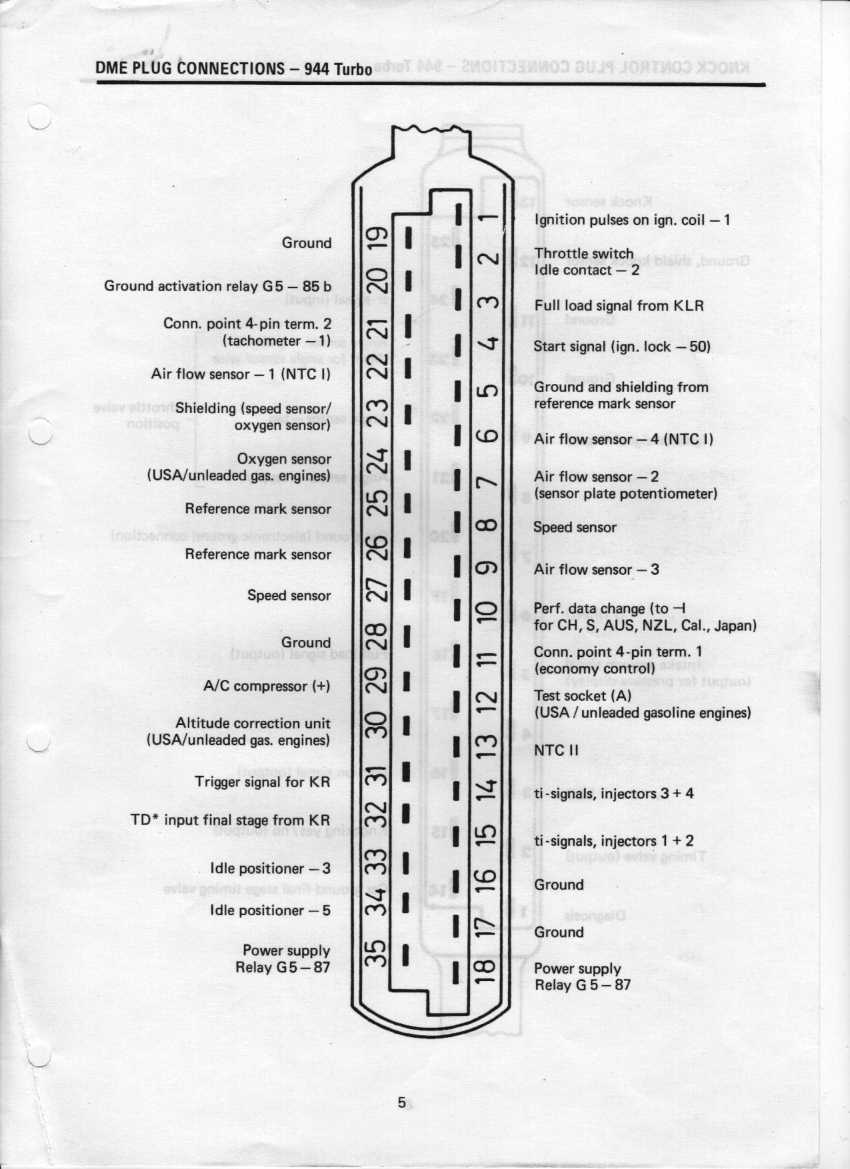
To do a continuity check on the signal wire, youd probably have to unplug the DME and use the pin there. That would be the best be if youre testing for a broken wire, which I assume you are. The pin you want is #24.
05-08-2009, 08:17 PM
#4
Rennlist Member
Thread Starter
Cool. Hopefully I'll be able to figure it out from there.
One question though.
Should the signal wire be grounded? (Should the red dot on the left plug in my picture have 0 resistance to ground?)
Edit:
From the way I read the diagram Brain gave me, it looks like both pins 1 and 3 should be grounded together. Which would make 12V across both, when tested with the meter would be correct.
Yeah...? lol.
05-08-2009, 10:00 PM
#5
Addict
Rennlist Member
Rennlist Member
Cool. Hopefully I'll be able to figure it out from there.
One question though.
Should the signal wire be grounded? (Should the red dot on the left plug in my picture have 0 resistance to ground?)
Edit:
From the way I read the diagram Brain gave me, it looks like both pins 1 and 3 should be grounded together. Which would make 12V across both, when tested with the meter would be correct.
Yeah...? lol.
One question though.
Should the signal wire be grounded? (Should the red dot on the left plug in my picture have 0 resistance to ground?)
Edit:
From the way I read the diagram Brain gave me, it looks like both pins 1 and 3 should be grounded together. Which would make 12V across both, when tested with the meter would be correct.
Yeah...? lol.
What youre seeing in the diagram (pins 1 and 3 connected) is the plug for Euro cars. That just grounds the signal wire out, but no north american cars would have come with that plug stock. In the wiring diagrams if you follow the wire from pin 3, youll see that its a "1.0 BR" wire, that means its 1MM squared in size, and colored brown. That symbol it leads to with D42 in it means a ground point.
05-11-2009, 06:15 PM
#6
Rennlist Member
Thread Starter
Figured it out why the signal wire was grounding.
I disconnected the harness from the DME and looked at the wires for the #24 and #23 pins, and one of the shielding wire strands was touching the pin. I had initially used adhesive lined heat shrink to make sure that didn't happen, but I guess a couple of the strands snuck out on me.
I got the little strands tucked away nicely, and now pin 1 (The red dot on the left connector) has infinite resistance with ground! WOOHOO!
Now my new O2 sensor should work just dandy. I hope...