Speedo still not working. Please Help.
 01-25-2009, 04:16 PM
#1
Rennlist Member
Thread Starter
I have replaced the sender at the transmission with a new one, and I have replaced the gauge cluster. All other gauges work fine.
What do I do now?
Does anyone know if the speedometer is run through the DME wiring harness at all?
I'm pretty sure it is not, but I'm not 100% on that.
Need suggestions... badly.
Thanks
What do I do now?
Does anyone know if the speedometer is run through the DME wiring harness at all?
I'm pretty sure it is not, but I'm not 100% on that.
Need suggestions... badly.
Thanks
 01-27-2009, 02:42 AM
#5
Rennlist Member
Thread Starter
I ordered a new pinion that drives the speed pulse sender. So I'll see if that somehow helps.
Please keep suggestions coming because I'm completely confused.
Please keep suggestions coming because I'm completely confused.

Trending Topics
01-27-2009, 03:06 PM
#8
The wiring diagram for my 86 NA says there is a Positive voltage connection from fuse 11 (area D6 of drawing which connects to area D17) to the transmission pickup. The other wire from the transmission pickup goes back to pin 14 on the instrument culster connection plug and from there to the speedometer. Maybe the fuse is blown?
01-27-2009, 07:01 PM
#9
Rennlist Member
Thread Starter
I checked the diagram and I think you followed the first line wrong, I think the fuse is fuse 18 for the instruments. Follow the line again and see if you agree with me, because, again, I'm not good at these things.
But I went out just now and checked fuse 11, and 18 and they were both fine.
If you follow the line and get to fuse 18 were I did, could you explain what all the stuff around that fuse means for me?
I REALLY REALLY appreciate the help!!
Oh... also... the speedo is the ONLY gauge that doesn't work.
But I went out just now and checked fuse 11, and 18 and they were both fine.
If you follow the line and get to fuse 18 were I did, could you explain what all the stuff around that fuse means for me?
I REALLY REALLY appreciate the help!!
Oh... also... the speedo is the ONLY gauge that doesn't work.
01-27-2009, 07:21 PM
#10
Nordschleife Master
The wiring diagram for my 86 NA says there is a Positive voltage connection from fuse 11 (area D6 of drawing which connects to area D17) to the transmission pickup. The other wire from the transmission pickup goes back to pin 14 on the instrument culster connection plug and from there to the speedometer. Maybe the fuse is blown?
I assume you have checked your grounds?
Using a multi meter check for continuity between the sender pins, 1-2 should be connected, neither should be connected to Pin3
MP II is the grounding point for the speed sensor, attached at the firewall. Use a multimeter to check Pin 3 of the harness connector at the speed sensor to the body of the car, value should be small,if not, your ground is bad.
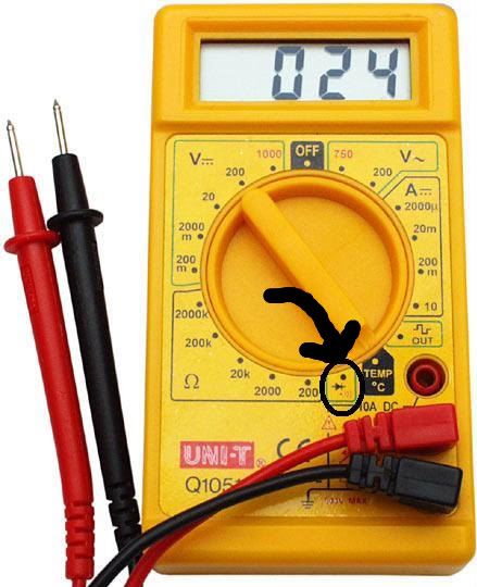
Next check Cluster Pin 14 to Pin 2, this would be the ground signal from the gauge cluster to the connector, if value is near 0 (use diode test on multimeter for tone) it is good.
Next Pin 1 to pin 4 of the instrument cluster, this is the + signal to the sensor, if this is good, continue..
If everything above is good, your problem is not the wiring, it is either your gauge, your sender, your relay, or a loose connection on the harness that you will have to wiggle wires to eliminate.
Good Luck...
Last edited by JohnKoaWood; 01-27-2009 at 07:40 PM.
01-27-2009, 07:39 PM
#11
Nordschleife Master
The bold dashed black line the the relay central electric panel (fuse and relay block). This is where fuse 18 is located. if you follow the wire up the page (on page 4) you will see a diamond (I19) this connects to the wire (pin 4 of the cluster) also showing the same I19 diamond (above and to the left on page 4).
Is this what you were looking for?
01-27-2009, 09:31 PM
#13
Nordschleife Master
 01-28-2009, 01:25 AM
#15
Rennlist Member
Thread Starter
Thanks forty... I just built a DME harness and was 99% sure but I wanted to be 100%.
And to john... I don't have that on my meter (I have a cheap one) will I be able to test without that mode?
And to john... I don't have that on my meter (I have a cheap one) will I be able to test without that mode?