Led's for Climate Control and Clock

 11-19-2007, 05:12 AM
#17
Racer
Join Date: Feb 2006
Location: Maryborough, Queensland, Australia.
Posts: 329
Likes: 0
Received 0 Likes
on
0 Posts
I havn't done a full conversion, but I did install the LED kit from Jager Engineering, and like it very much.
http://jageng.com/garage9/product_in...0a7f2c7d55f091
http://jageng.com/garage9/product_in...0a7f2c7d55f091
11-19-2007, 08:33 AM
#18
Burning Brakes
Join Date: Mar 2006
Location: Orlando,FL (formerly UK)
Posts: 1,215
Likes: 0
Received 0 Likes
on
0 Posts
I'll be doing a complete LED upgrade in the next few weeks.
I'm not buying LED bulbs: instead I'll be doing it the "hardcore" way, with OEM LEDs and current-limiting resistors. The climate and clock will be getting the same treatment.
I'll be taking pictures and documenting the procedure, but how many people here are okay with rectifier diodes, resistors, LEDs and a soldering iron?
Oh, and I'll also be upgrading the interior dome light to a more modern-looking unit, and incorporating a short delay and a 'soft-off' circuit for that, as well as making that LED also.
Keith
11-19-2007, 10:06 AM
#19
Burning Brakes
I've got the Jaeger LEDs but haven't installed them yet. I was considering replacing the other bulbs in the clock and HVAC controls with bulbs from superbrightleds.com. There was a thread a few weeks back with a recommendation for bulbs from them. They're fairly inexpensive so it's worth a shot.
11-19-2007, 01:33 PM
#22
Instructor
Thread Starter

Join Date: Oct 2007
Location: Everett, WA
Posts: 138
Likes: 0
Received 0 Likes
on
0 Posts
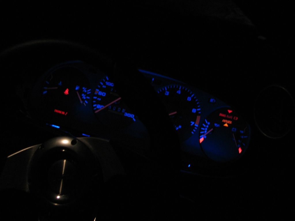
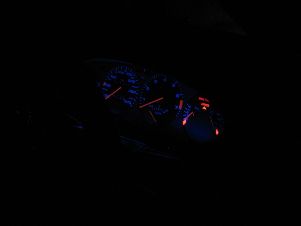
VWaddict, When you do it please list it in this thread and please give links and decription of what you used! The blue leds you have seem dimmer then mine! Does the camara drown the color? Cause mine are close to same brightness as there pictures on the website! I also used aluminum for the reflectors!
11-19-2007, 02:38 PM
#23
Race Car
I'll be doing a complete LED upgrade in the next few weeks.
I'm not buying LED bulbs: instead I'll be doing it the "hardcore" way, with OEM LEDs and current-limiting resistors. The climate and clock will be getting the same treatment.
I'll be taking pictures and documenting the procedure, but how many people here are okay with rectifier diodes, resistors, LEDs and a soldering iron?
Oh, and I'll also be upgrading the interior dome light to a more modern-looking unit, and incorporating a short delay and a 'soft-off' circuit for that, as well as making that LED also.
Keith
I'm not buying LED bulbs: instead I'll be doing it the "hardcore" way, with OEM LEDs and current-limiting resistors. The climate and clock will be getting the same treatment.
I'll be taking pictures and documenting the procedure, but how many people here are okay with rectifier diodes, resistors, LEDs and a soldering iron?
Oh, and I'll also be upgrading the interior dome light to a more modern-looking unit, and incorporating a short delay and a 'soft-off' circuit for that, as well as making that LED also.
Keith

I built my own bulb assemblies with a resistor and 2 LEDs tucked into each one then replaced the 3 main lights for the instrument cluster. I started going around changing every other bulb as well but I never got the time due to other issues on the car and school. I did change the LED in the clock out as well. A word for the wise, in the clock your LED should point completely sideways. Yes it seems weird
 11-19-2007, 07:30 PM
#24
Burning Brakes
Join Date: Mar 2006
Location: Orlando,FL (formerly UK)
Posts: 1,215
Likes: 0
Received 0 Likes
on
0 Posts
except...
Many of the LED types out there on the market have low PIV (maximum reverse voltage before breakdown/failure), so if you get them in backwards, you can destroy the junction. The idea of putting rectifier diodes in would be solely to make them fully reversible. -That way, not only would they be protected from reverse junction biasing, they'd even light up installed either way round!
-If you go with one of the "off-the-shelf" LED bulb-replacement 'lamps' with something physically reversible such as a festoon bulb (like the interior dome light) or the wedge-base types (type number 194 etc) it will have anti-reverse rectification already built-in, for this exact reason.
Of course, if you KNOW the polarity at the bulb socket, and you can be assured of getting the LED in the right way round, you don't need the rectifier, but if you do get them reversed, prolonged exposure to reverse bias may kill the LED... -You have to look at the spec sheet for the LED itself, and remember that it's getting the FULL 12-14Volts when it's reversed, since the resistor won't help by dropping any volts for you when the junction is reversed.
..Which is why I was going to use anti-reverse rectifiers for the 'how-to'. Not so much because they're needed if nobody ever gets one in backwards, but because they're a good idea if anybody ever does.
Here's a data sheet for a typical white LED by way of illustration:
http://www.lc-led.com/products/500tsw4df.html
In addition, there are LOTS of diffferent types of LED out there. Different colours will have different VFwd ratings (forward bias voltage),which will affect the series resistor value for same luminous intensity output, also different Imax (max. rated current before breakdown/failure). It's unlikely that any will burn once forward-biased if you're only running 15mA or so through them... -it's been a while since I had hold of any LEDs with a lower Imax than 20mA- but I thought I should build a table or excel sheet for download, so that if anyone wants to use their own LEDs for whatever reason- then they can put the various numbers from the datasheet into the spreadsheet and work from there.
There are other tricks also, such as wiring a reversed zener in series with the LED, to make it more affected by the dash dimmer control: for example, if your LED has a 4V Vfwd, it will be dark only when the supply voltage falls below 4Volts. If you put a 5V Zener in (reversed) series with it, it will be dark for all voltages below 9V... Adjust the series resistor to give the same brightness at 14.5V, and now you have a device which is rather more sensitive to varying dimmer voltages, which is one way to remedy a complaint that many people have voiced about switching to LEDs.
Notice that the forward drop voltage is 4Volts, but the reverse voltage that it can stand is 5Volts... You wire it in backwards and you can fry it... unless you either add a bridge rectifier or "reverse-clamp" it with a signal diode in cross-parallel. (though this method doesn't make the LED work both ways, it does at least keep the LED from burning up... though the series resistor gets a bit warm while it's in backwards!)
I probably got into it more than I needed to, but I do want to make it clear that I've given the idea a lot of thought, and I'd like to make the idea as bullet-proof as possible, so that anyone else who goes along with the "how-to" later on has a better chance of getting it to work first time.
Keith
11-19-2007, 07:40 PM
#25
Burning Brakes
Join Date: Mar 2006
Location: Orlando,FL (formerly UK)
Posts: 1,215
Likes: 0
Received 0 Likes
on
0 Posts
Oh, one more thought: There's a 'hybrid' white LED, which is actually an ultra-violet diode, which puts out UV light which then causes a white floursecent substance to emit white light... using exactly the same principle to fluorescent tubes in house lighting... but since certain types of paint are alsu fluorsecent to a varying degree, it would be interesting if the paint on our dash lettering and needles fluoresced under ultra-violet light... then you could just put in UV LEDs, and have a very groovy display...
But I've no idea if it does or not. -If anyone has a strong UV source anywhere near their car, that they could shine onto the dash at night, I'd be VERY interested in finding out what it looks like...
Cheers!
Keith
But I've no idea if it does or not. -If anyone has a strong UV source anywhere near their car, that they could shine onto the dash at night, I'd be VERY interested in finding out what it looks like...
Cheers!
Keith
11-19-2007, 09:57 PM
#27
Burning Brakes
Join Date: Mar 2006
Location: Orlando,FL (formerly UK)
Posts: 1,215
Likes: 0
Received 0 Likes
on
0 Posts
Yes, exactly. -Although all a bridge rectifier is, is 4 diodes in a particular arrangement, so it's really not difficult. -A simple layout 'map' is all everyone should need.

Keith
Keith
11-22-2007, 07:20 AM
#28
Instructor
Thread Starter
Join Date: Oct 2007
Location: Everett, WA
Posts: 138
Likes: 0
Received 0 Likes
on
0 Posts
Man you guys are talking up a storm! Anyways VWaddict, when you get everything done can you make make sure you do a full write up along with were you got the led's from and resistos and the diodes aswell! Cause I would like to tackel this and I am sure many others would aswell!
11-22-2007, 07:54 AM
#29
Rennlist Member
One thing I don't like about the LED conversion is that I believe the rheostat (dimmer dial switch) will no longer work to adjust the lighting brightness.
Not that I use it much now, but you need to be careful not to end up with an instrument panel that's too bright or your night driving visibility will be compromised.
I'll probably just replace the bulbs with new units and be done with it.
Not that I use it much now, but you need to be careful not to end up with an instrument panel that's too bright or your night driving visibility will be compromised.
I'll probably just replace the bulbs with new units and be done with it.
11-22-2007, 10:58 AM
#30
Burning Brakes
Join Date: Mar 2006
Location: Orlando,FL (formerly UK)
Posts: 1,215
Likes: 0
Received 0 Likes
on
0 Posts
The rheostat will work progressively less effectively the less current is fed through it. -The bad news?- LEDs draw much less current.
HOWEVER, It is correctible. The rheostat can be retrofitted (pretty easily if it's a � shaft control) with a simple, inexpensive variable-voltage dimmer circuit, which can use the original wiring...
Anyone got pictures of the rehesotat behind the panel.. to save me stripping the panel off and then having to reassemble it just to go to work on Friday!
Keith