When you click on links to various merchants on this site and make a purchase, this can result in this site earning a commission. Affiliate programs and affiliations include, but are not limited to, the eBay Partner Network.
Hi All,
First time posting, I am looking for some guidance on a no reading temperature gauge. I have searched the forum and some people seem to have experienced a similar problem, but not exactly the same one. We're talking 89' S2.... I'm in the UK.
Put simply, I have no temperature gauge readout. If I pull the two terminals off and earth them both I get the temp warning light come on. Therefore, I'm getting a good ground during that test. If I then ground out the other wire, I just cant get the gauge to budge. Reading some other posts, it appears the actual gauge in the dash has potential to become sticky and be stuck in one position (cold, in my case). Oh..... the car has been sitting for a number of years!!!!
Obviously the test is carried with the ignition on, but engine not running. Also I don't currently have the fans plugged in - but I don't see that that should make any difference.
I don't know if the sensor is any good, but that doesn't really make any odds as I'm just trying to get something to read on the dash.
Good people of Rennlist... what is the next best step? crack open the dash and check the gauge? Or start chasing through to see if I have a bad connection on the wire? Or something else???
Any help or guidance would be most appreciated. Thanks
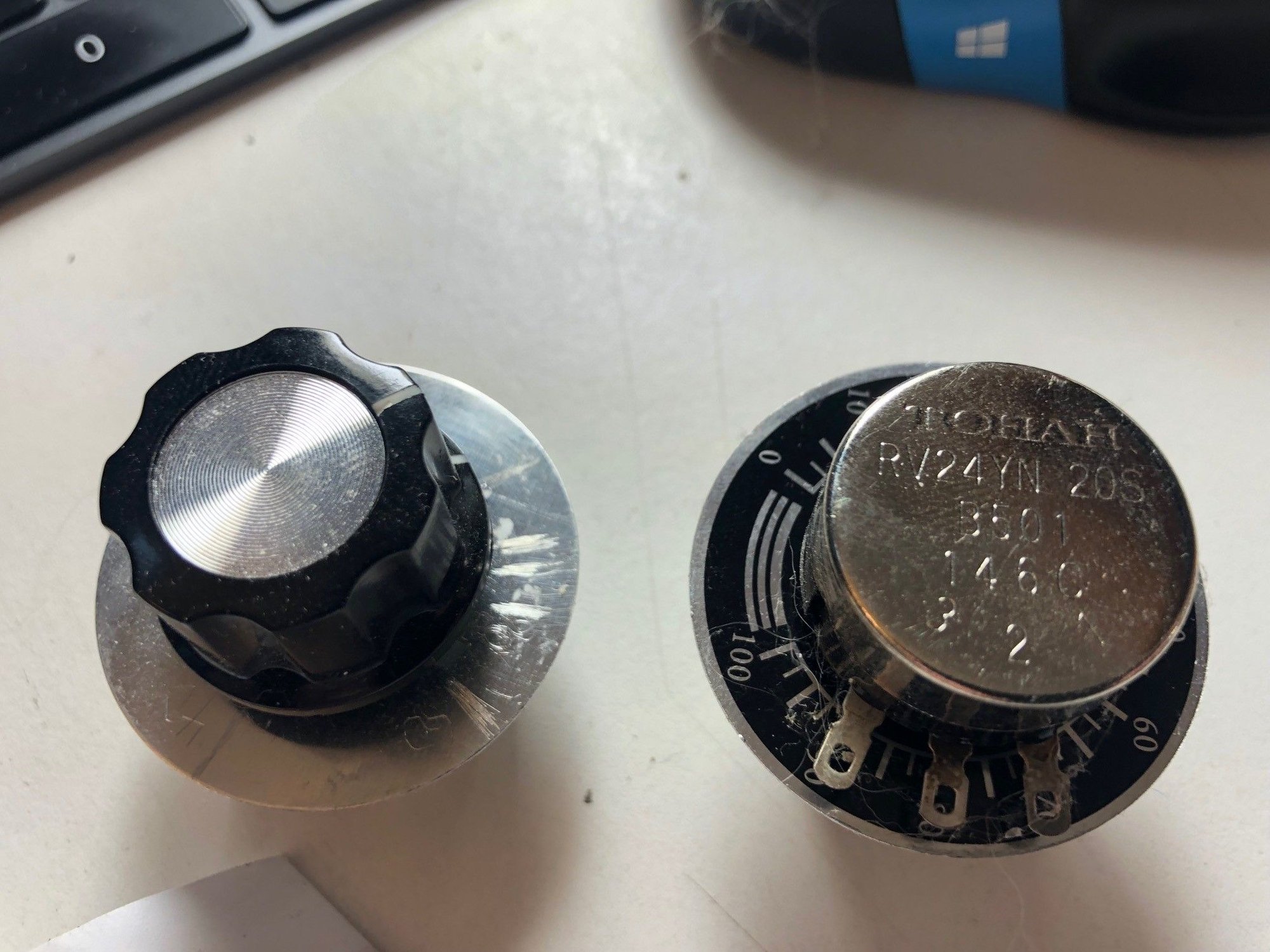
+1 on Sixline's suggestion. I've attached a picture of the "variable potentiometer" that I used with Clark's instructions. Came in a 2-pack from Amazon.
The etching marks you see on the silver (backside) of one of the potentiometers correspond to specific temperatures on the dash. (The markings on the black side didn't correspond to any real temperature.)
Thanks for the response, yes I will test the sensor in time to see if I need to replace it. (weekend coming I guess)
However, I have pulled the spade connectors off the sensor and I'm grounding those to test the gauge on the dash.
Any other thoughts anyone? I can't get a response from the gauge.....
Thanks
One wire is for the warning light and the other is for the sensor. Grounding the one for the light will turn the light on. I am not sure if grounding the sensor wire will cause the gauge to peg or not.
If the sensor resistance checks out and the gauge is still showing nothing then you have either a wiring or gauge problem.
Grounding the other wire should cause the sensor to peg to max (at least if it's wired the same way as the oil pressure gauge). I'd suspect the card-edge-connector on the back of the instrument cluster....
So I've tested the sensor and everything seems to check out. At room temperature the large spade connector (gauge feed) has a resistance of 453 Ohms. At 70�C it has a resistance of 93 Ohms. So it appears to be working more than adequately.
I feel I now have two options. Trace the wiring and test at each junction or go straight for the jugular and assume there is something wrong in the dash.
I have the wiring diagram but I must confess I'm unsure which plug in the fuse box area the wire goes to. The sensor is on pdf page 202 on volume 5 of the workshop manual. Or sheet 97-249 (944 S Model 91 Sheet 7). The blue and yellow wire I am chasing goes into 'Connection DME' T21 - is that the name of the plug?
I suppose one thing to do is to check for a connection at the dash all the way back to the spade connector. That will rule out or rule in the wiring.
The instrument cluster is (slightly) easier to deal with than the back of the "central electric" (aka the fuseboard). I'd start with checking connectivity from the instrument cluster to the sensor.
ok, sold. I was thinking the same. The glove box does happen to be out at the moment as I had two alarms and a immobiliser removed (kept the Porsche alarm).
I can see the back of the central electric. Lots of plugs, I would want to know exactly which one it is before yanking anything.
I had seen that cover and thought at a glance that it was a junction of three looms, not just a nice plug.
I was able to check for continuity - all good. I also checked the actually resistance - 0.3Ohms. So all good there.
I guess I'll tackle the dash next unless anyone knows the next convenient break in the loom? I had a look at the central electric and I'm not going to touch it unless I have to.....
So.....
I took the instrument cluster out... Someone has been in there previously and broken some of the plug fittings. I tested the wire all the way from the sensor to the spade connector - it appears to be all good. (Plug A pin number 12)
Have you tried it again with just cleaning the edge connector? (That fixed my oil pressure gauge.)
Next would be cleaning the copper on the flexible plastic circuit board where the two screw posts from the temp gauge come through (under the little plastic bridge between them).
Only after that would I dig into the instruments themselves.
I have tested the instrument cluster and the gauge is working. However I did do the two screw post clean thing that @jeyjey mentions above that I saw on Pelican parts forum. There was a slight hint of white between the contacts. Unfortunately I did this and then tested the instrument gauge. All working ok.
or information, pin 4 (black wire on plug) provides power to this area of the board and pin 12 grounds out the gauge. It pegs straight to max with 12v across it. I used a current limited power supply for this. I don't recommend using a 12v battery.
I may have fixed it by cleaning the contacts, I won't know until I can put it back together and test all the way from the sensor spade connector up to the cluster. I'll put it all back together in daylight and have a check.

 08-16-2021 | 06:35 PM