When you click on links to various merchants on this site and make a purchase, this can result in this site earning a commission. Affiliate programs and affiliations include, but are not limited to, the eBay Partner Network.
Dual VR Conditioner Board V2.1
Small enough to solder onto the proto area on your board
I definitely like the MAX9926 that is used on that board, certainly better than the VR circuit in the MicroSquirt. I will likely incorporate that chip if/when I switch to using the stock sensors.
Originally Posted by Dwizle
Also, the micro squirt doesn't have the code to run 951 or non S2 flywheel set up MS3 has the code called Tri-Tach in tuner studio
Yep, this is the real issue w.r.t. using the stock sensors. The MicroSquirt software just can't support it (e.g., it demands that the number of teeth be an integral divisor of 3600). The MS3 can do it, but there is no MS3 "module" that is legal to use in a custom design (without license fees), even for a hobbyist. And I'm not particularly interesting in using one of the off-the-shelf MS mainboards.
That's why I'm shelving any notion of using the stock sensors / flywheel for now and sticking with the 36-1 wheel and hall sensor. Sometime later, when I pick this issue up again, I will seriously look at jumping ship to a custom Speeduino ECU based on a Cortext-M4 processor (e.g. a Teensy 3.x). I'm finding the MegaSquirt stuff to be a little too closed/restrictive for my taste.
Great minds think alike! I just bought a few of these from connectorpeople.com just to have around. It used to be that you could get these from Mouser, but last I looked they were no longer available.
These connectors are nearly identical to the ones used on the early ECU, the only difference being the length of the pins (the ones on the early ECUs are longer).
The downside to these connectors is that there is no built-in retaining mechanism for the harness connector. Bad news if it falls out on the track! Push comes to shove, if you were using this in a custom enclosure, you could probably just use a long velcro strap around the whole enclosure to keep the connector in place.
Actually I drove around with one for a year never had it come lose it was actually a pin in the *** to take apart
I definitely like the MAX9926 that is used on that board, certainly better than the VR circuit in the MicroSquirt. I will likely incorporate that chip if/when I switch to using the stock sensors.
Yep, this is the real issue w.r.t. using the stock sensors. The MicroSquirt software just can't support it (e.g., it demands that the number of teeth be an integral divisor of 3600). The MS3 can do it, but there is no MS3 "module" that is legal to use in a custom design (without license fees), even for a hobbyist. And I'm not particularly interesting in using one of the off-the-shelf MS mainboards.
That's why I'm shelving any notion of using the stock sensors / flywheel for now and sticking with the 36-1 wheel and hall sensor. Sometime later, when I pick this issue up again, I will seriously look at jumping ship to a custom Speeduino ECU based on a Cortext-M4 processor (e.g. a Teensy 3.x). I'm finding the MegaSquirt stuff to be a little too closed/restrictive for my taste.
https://www.diyautotune.com/product/ms3-pro-module/
I found this on diyautotune I purchased one and have been in the process of trying to design a board for the 944/951 ever since I saw your board design.
waiting for the first 5 boards to show up but already found issues so I am working on a redesign.
Great minds think alike! I just bought a few of these from connectorpeople.com just to have around. It used to be that you could get these from Mouser, but last I looked they were no longer available.
These connectors are nearly identical to the ones used on the early ECU, the only difference being the length of the pins (the ones on the early ECUs are longer).
The downside to these connectors is that there is no built-in retaining mechanism for the harness connector. Bad news if it falls out on the track! Push comes to shove, if you were using this in a custom enclosure, you could probably just use a long velcro strap around the whole enclosure to keep the connector in place.
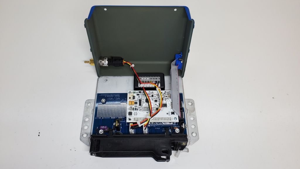
For anyone still following along, I've been working on a bracket for a front mount crank position sensor. Details on the design can be found here: Front crank sensor mount
Meanwhile, I've completed the internals of the ECU:
Did you ever figure out a part number for the connector you used? aAso, what is the part number to the map sensor you used?
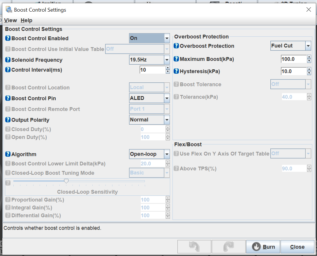
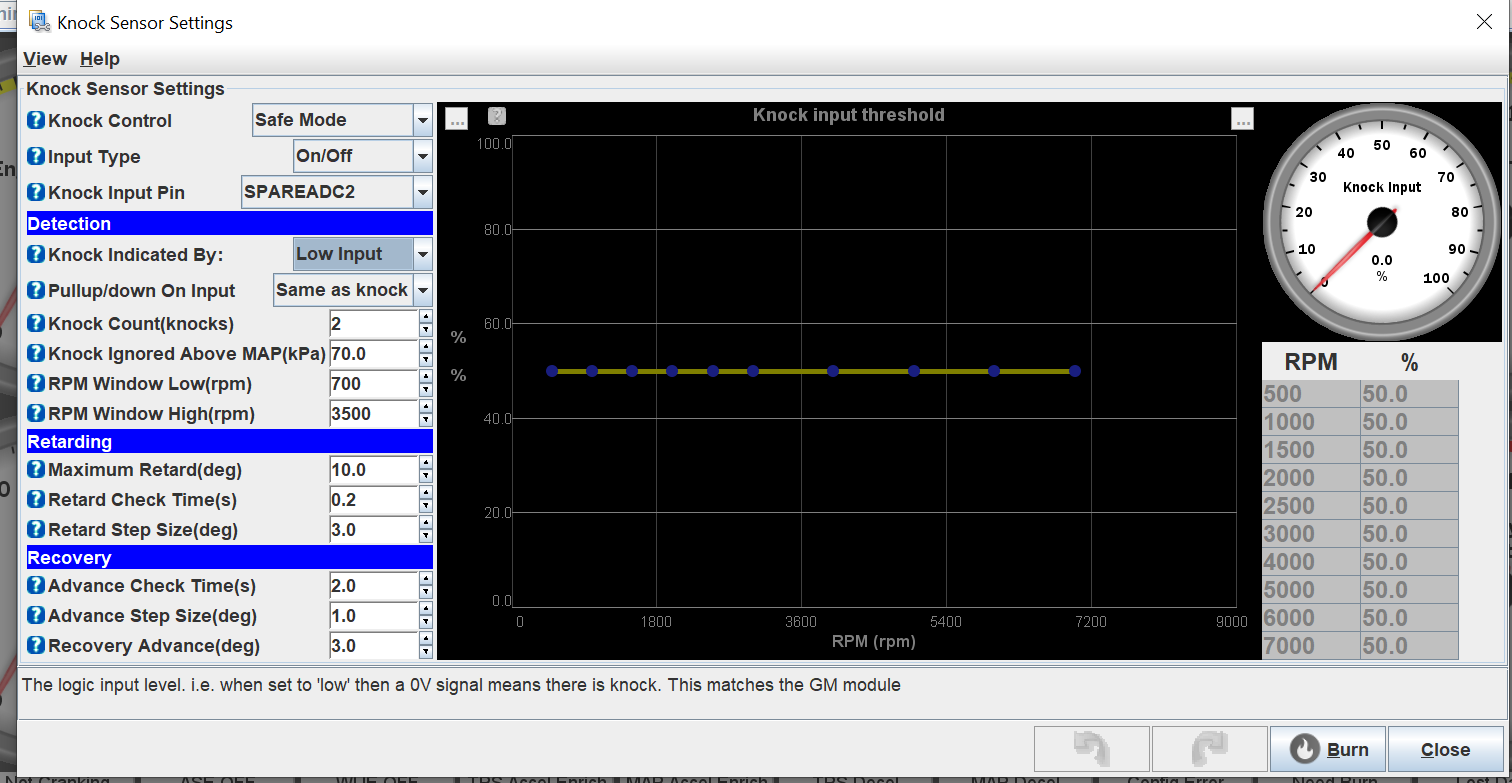
Getting ready for the initial fire - excited but somewhat nervous. Would you mind sharing your settings in TS for the knock setup table and Boost control table? I am using the stock knock sensor and a knocksense module. For boost control I have the MAC 12v boost controller. I just don't want to screw something up.
 09-12-2020, 10:03 PM