When you click on links to various merchants on this site and make a purchase, this can result in this site earning a commission. Affiliate programs and affiliations include, but are not limited to, the eBay Partner Network.
Dare: regarding finding a dead DME, are you a member of any of those 944 Facebook pages? Easiest way to quickly get a part these days. If all else fails drop me a line, I have a buddy with a pile of DMEs and I'm sure he would send you one for very little.
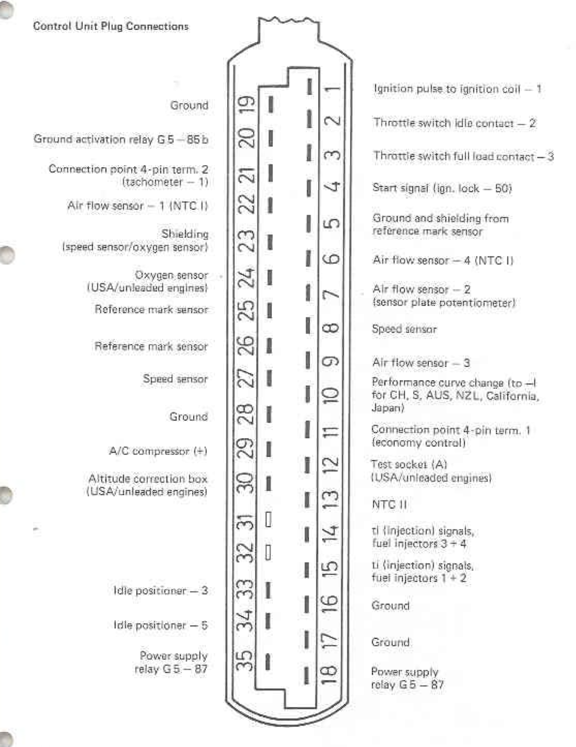
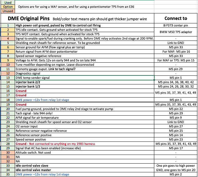
So onto the pin assignments. This is what I have been able to figure out:
Some discussion on the above:
The bolded or colored text means that the thicker jumper wires should be used instead of normal 36 AWG. I ordered 28 AWG.
You will see there are 'options' for a MAF and for a BMW TPS sensor. I will discuss more on this later. I am using a MAF but this is not typical for most installations, MAP/speed density is fine unless you live in an area with huge elevation changes. The TPS sensor is highly recommended however, as you will get better throttle tip-in response. The stock 944 sensor is not capable of providing this information to MS so an E36 part is used instead. More info to come soon.
Pin 11 is the economy signal. You don't need this connected. However, I found references that it has a role in the tachometer signal in the late 944. There is also Pin 21, which is called tach signal, but this doesn't exist on my early 944 harness. I am still looking through wiring diagrams but if anyone knows which of these pins is the true source of the tach signal, please drop a line!
Pins 33/34 are only utilized on a late 944. The early 944 has an "auxiliary air valve" which operates independently of the ECU. Late 944 has a PWM-controlled idle valve, which MS will run. To convert the 3-pin IAC into something MS can control, one half will be pulled to ground and MS will just tell it when to open. More on this later.
Pin 29 told the DME when the AC compressor clutch was kicked on, and the tune was changed to keep the idle speed proper. MS has many inputs/outputs that are user-defined so we can do the same.
The new cam speed sensor will fill the role of the stock speed sensor. However it will need switched 12v from outside the harness. This will be discussed later. The signal from the sensor, as well as its ground, are passed through the stock harness.
Another discovery I made was the stock DME coolant temp sensor (blue connector) and the stock TPS don't ground through the DME. This is not what I had assumed as first, usually you want to give your sensors a dedicated ground back to the ECU for the best possible reading. Instead, they actually ground at the bellhousing. There are 2 ground points there from the stock wiring harness. The larger lug goes to the ground points you see in the chart I posted above, for the DME (except I had 1 pin with no continuity, not sure why). The smaller lug goes to these sensors plus potentially some other stuff. So when installing this ECU, it will be absolutely mandatory that these grounds are taken apart and cleaned until they sparkle!
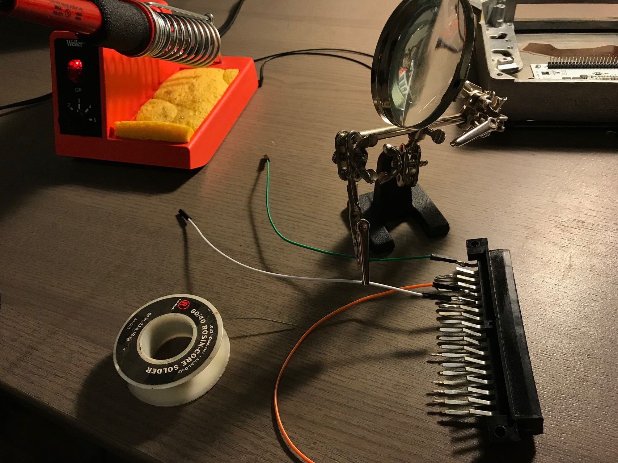
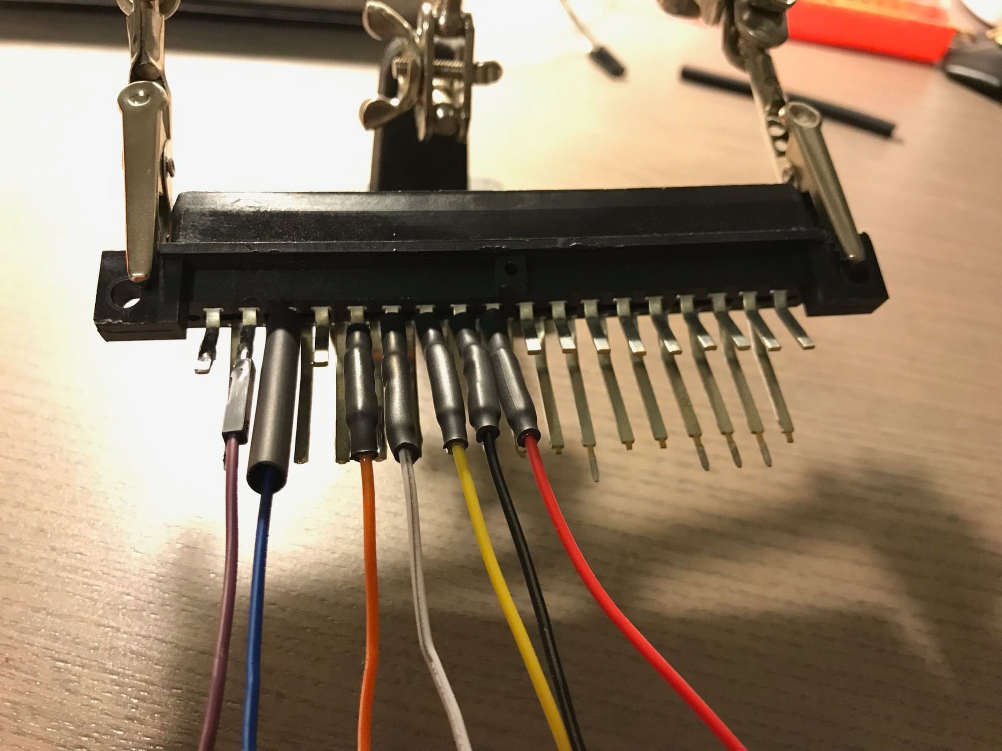
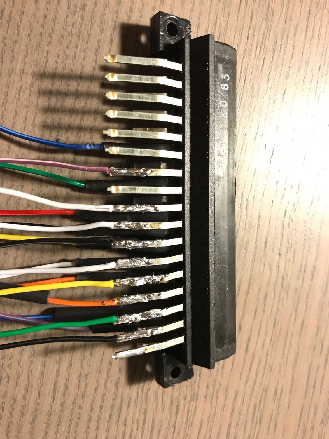
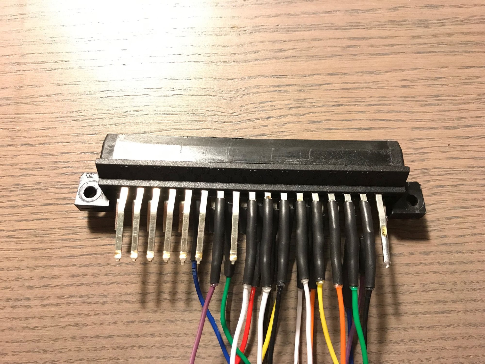
For physical implementation, I have added the jumpers that don't need the thicker wire since I'm still waiting on those. I tried 2 approached. First, directly soldering the male pin to the DME connector pin. This works but I much prefer cutting off the male pin and stripping the wire to get a bare end. Then, solder this to the pin. In both cases I cleaned the DME pin with acetone (to remove any conformal coating leftover from manufacturing) and used adhesive-lined heat shrink sleeves + heat gun. First 2 pictures show the direct pin soldering, the last 2 show the preferred method.
Michael, I think the choice of adhesive-lined shrink tubing is good, as you'll want a lot of support against vibration for those soldered connections, especially with the leads cantilevered like that. Looking at the pictures I might position the shrink tubing a little more over the wire insulation to make sure there's a good mechanical connection.
Also the solder joints look a little gloppy. Is your iron hot enough? This might be an issue for the DIYer with a low-power iron, as those connector leads will soak up a lot of heat.
Regarding the grounds, its possibly different for the early/NA cars, but on my '86 951 the TPS ground goes to Weld Point 4, which is a pressure weld located roughly in the non-ribbed part of the snorkel. From there there are separate wires to pins 5 and 28 on the DME, and the big wire to the engine block ground point (all detailed in my harness wire list spreadsheet, FYI). Your point about cleaning the engine grounds is spot on, though. Probably save people a lot of trouble down the line.
Thanks for the feedback - I agree the solder joints don't look great. I will try increasing the temp. I initially bought this adjustable Weller station because in the past, my bad habit was to overcook solder joints. Still learning! Used to wire/wire connection and small through-hole soldering. And I will take your advice on the heatshrink position as well. I may remove all of these and start over, although mechanically they seem very strong.
Regarding the 951 TPS ground, it's a bit different as the TPS signal goes through the KLR. I'll use your spreadsheet as reference material. Thanks!
Been super busy the last few weeks and haven't made much progress. However, tonight I had some time and got the MS talking to my laptop. So far it's working as expected. I had a few bad jumper wires right out of the box, which slowed my progress and I prioritized other projects due to the roadblock. I'll be working on this more, but I will be traveling for work on and off through April and will update when I can.
I also upped the heat on my soldering iron, redid most of the joints and they're better (although a far cry from perfect). Thanks again for the feedback Dare, I greatly appreciate all constructive criticism.
Looking good, Michael! Those jumpers are notoriously bad. There's always a couple bad ones in the lot.
I have a little progress of my own to report: ordered and received a MicroSquirt, hall sensor and a couple of driver transistors (BIP373s). Found a dead early DME ($40) on Facebook (thanks for the suggestion!), which I've since torn down. I also picked up a DME for 90's Saab 900 Turbo ($25). I like the Saab DME because its the same case and connector configuration as the late 944 DME; plus the internal arrangement is very conducive to mounting your own PCB (like this), more so than the early DME.
I managed to pull the harness connector off the Saab board by drilling out the mounting holes and desoldering the pins with a $40 hot air station. I then found a pad-per-hole prototype board which is an exact fit width-wise for the Saab board. After drilling a few holes to pick up the existing mounting points on the DME base plate, I have a pretty good platform on which to mount the MS and supporting components and do point-to-point wiring. (Some pictures in my album).
Next up: finish the wiring list for the harness and build a schematic for the protoboard.
I'm glad the SAAB ECU worked for you! I'll be watching to see weather or not I want to take the same plunge!
Almost all of the jumper wires are hooked up to their assigned pins. I'll be doing some wire management to keep them organized. My next task is connecting the wires that require a splitter (some pins go to multiple pins). I tried manually building these by cutting and splicing but I got non-continuity. Not sure what's going on, it's something I've done many times before with thicker gauge wire. So I'll just try and find some ready-made online.
Then, it's time to mount the BIP373 coil driver and MAP sensor. The ECU will be ready to plug in after that.
Sorry guys, been caught up with moving recently and have been slammed at work. Not much progress has been made. In fact I think it's still packed in a box somewhere.
However in the next month (I hope?) there will be a donor 944 coming to Houston that will serve as the test mule.

 01-05-2019, 05:39 PM