When you click on links to various merchants on this site and make a purchase, this can result in this site earning a commission. Affiliate programs and affiliations include, but are not limited to, the eBay Partner Network.
I have picked up a spare alternator and starter for my Red Witch. I sourced them through an L.A. salvage yard. My intent was to:
-disassemble
-quick inspection
-thorough cleaning
-closer inspection
-component testing
-replacement of failed or worn components
-reassembly
-unit testing
I started with the alternator. It was listed as being from a 1986 928, with mfr part number of 92860301101.
The unit was suprisingly clean, and had a Bosch 'Premium' sticker on the side. My impression was that this was a Bosch remanufactured unit that was fitted to the vehicle at some point prior to entering the salvage yard.
Under the Bosch 'Premium' sticker was a Bosch ID sticker. Part number was 0 120 468 005, and appeared to be a 115A unit. Also on the label was a Porsche number of 928 603 011 05.
I noticed the noise supressor was a Bosch item. The voltage regulator was not. It had the markings "LB 04 591" on it. The brushes were quite long.After match marking the case halves, I split the case. Inside, I noticed everything was relatively clean. The bearings looked new. The slip rings did not look bad. They were not new, and might not have been turned when the unit was remanufactured. They show very light grooving. There were no obvious signs of overheating on the rectifier assembly.
I removed the bearings from the rotor shaft, being careful not to damage the front bearing retainer plate. The rear bearing was an NSK 6201, made in Poland. I was pleased to see the rear bearing plastic retainer was in new condition. The front bearing was an NTN 6303, made in Japan. Both bearings looked new, and spun smoothly. However, I had new Nachi bearings to go on, and I had pulled these off. This made them unusable.
The front and rear case halves, bearing retainer plate, fan, pulley, and all hardware went into the heated parts washer for a good soak. The rotor, stator, rectifier, voltage regulator/brush holder, and noise supressor were thoroughly cleaned with contact cleaner, then allowed to dry.
I dressed the slip rings lightly with a red scotchbrite pad on a slow speed lathe. They cleaned up well.
Component testing was for the stator, rotor, and diodes in the rectifer. Slip rings on the rotor had good continuity with each other, on the order of 0.2 ohms. Slip rings were open to the rotor shaft. The stator windings had good continuity with each other, on the order of 0.2 ohms. The windings were open to the stator frame. All the diodes checked out good in the rectifer. Forward bias was 0.439VDC, reverse bias was open.
I fitted the front bearing into the front case half, with a light coat of antiseize on the outer race. I carefully pressed the rear bearing on to the rotor with a hydrualic press and socket, then did the same with the front case half/bearing, and front bearing retainer washer.
Reassembly was reverse of disassembly. I used a drop of purple low strength Loctite on all threaded fasteners.
I did not refit the voltage regulator, as I am using a remote adjustable regulator from Dave Barton's Volvo page.
My next step is to take the alternator to a FLAPS and have it tested. I am going to see if they will test it with the remote regulator as well as the installed regulator.
In July, when I install the new (+) battery cable, I will install this refurbished alternator. Then, I will repeat the above process on the removed alternator. This will give me a known good spare alternator on the shelf.
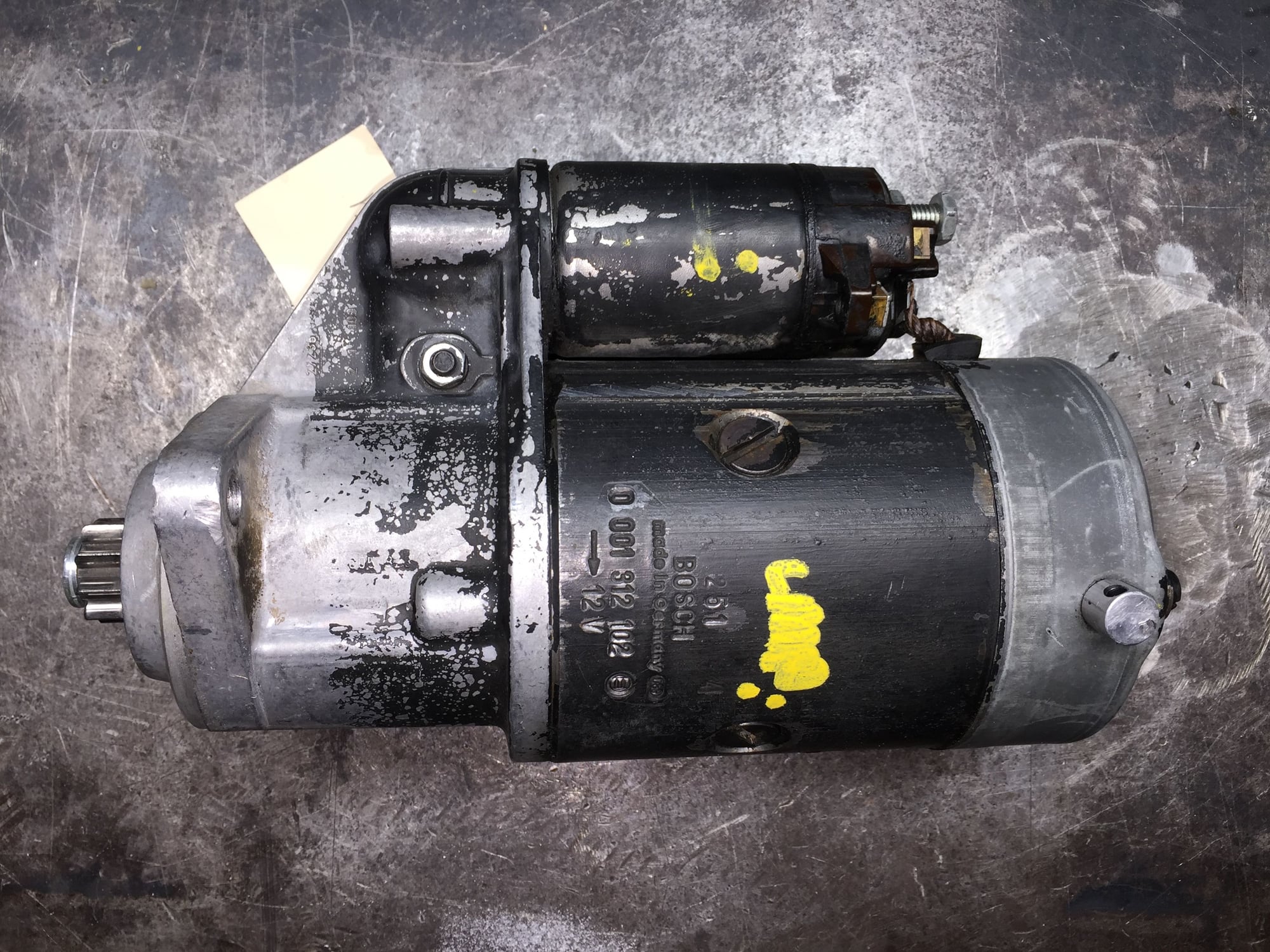
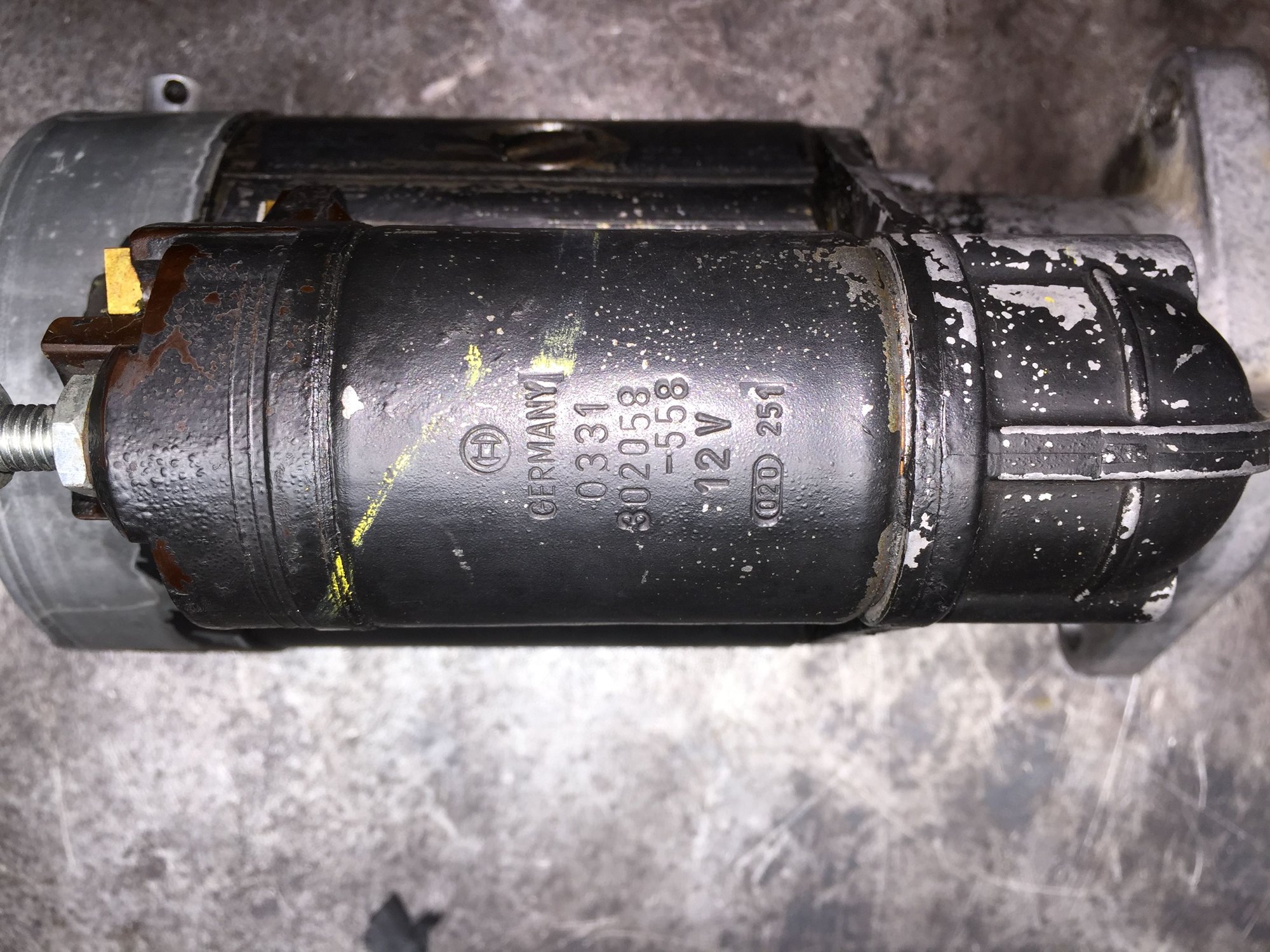
Onto the starter. It was listed as being from a 1983 928, with Porsche number 92857426904, and mfr number 0001312102.
Based upon the coating of paint on the solenoid, I don't believe this starter is a reman unit. So, I expected to have some work ahead of me. After reading Rob Edward's thread on starter rebuild, I bought the same starter brush/bushing kit he did from ebay.
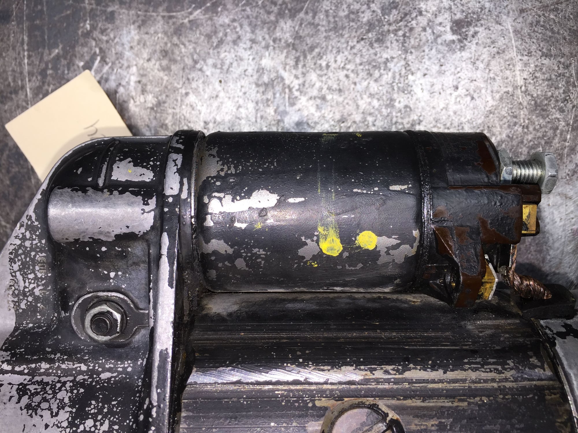
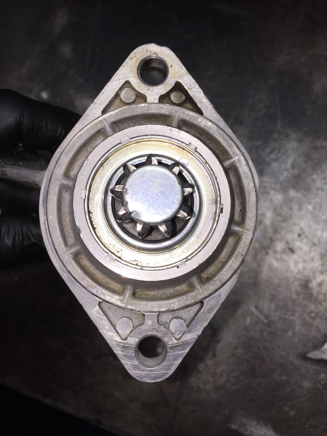
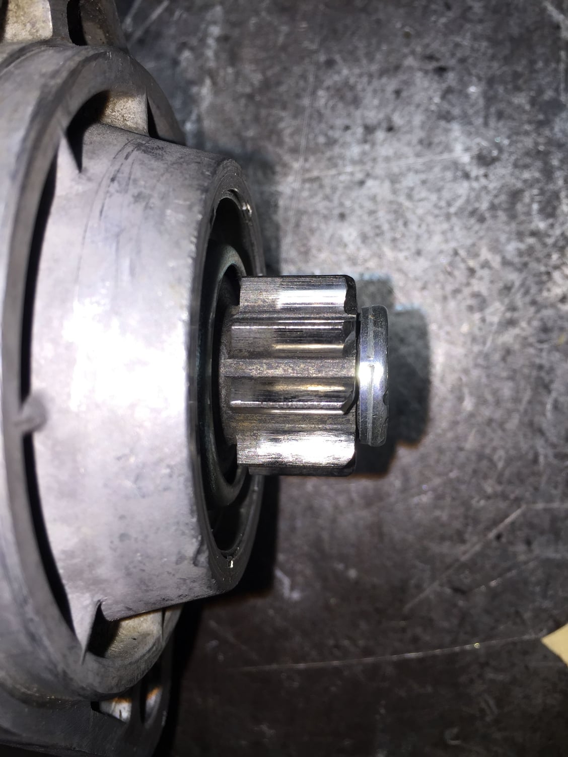
On the outside, the starter looked to be in good condition. The drive pinion teeth looked good. They had what I consider to be normal wear, with no nicks or damaged teeth.
The starter mounting ears were not cracked, and the wiring lugs on the solenoid were not damaged.
I disassembled the starter in the order of:
-solenoid
-end bushing cover
-shaft retaining ring and washer
-end cap
-brush plate
-casing
-armature and linkage
The plunger end of the solenoid had some thick oil/thin grease crud on it.
The underside of the end cap and the top of the brush plate had some oil on them. I am not sure if this is from lubrication of the bushing or something that had leaked in. I don't think leak, because the starter was not full of oil.
The brush end of the starter was covered in a fine layer of brush dust.
To remove the (+) brushes from the brush plate, I used a 90 degree pick tool to lever the spiral spring out of the way. Years of working on 36VDC forklift electric motors taught me that trick.
First good sign was that the brushes looked surprisingly good. Next good sign, so did the commutator. I was not comfortable chucking the armature up in a lathe due to such a short stub shaft. So, I worked the commutator by hand with a piece of red scotchbrite pad. It cleaned up quite well.
The aluminum drive housing, end cap, bushing cover, drive yoke lever, and all hardware went for a bath in the heated parts washer.
The armature, casing, brush plate, and solenoid were thoroughly cleaned with contact cleaner. I saw no unusual wear or damage on any of the items.
The brushes visually looked slightly shorter than the new ones. I elected not to change them. The old bushings' ID's measured within a couple of hundredths of a millimeter of the new ones, via my digital calipers. So, either the old bushings are that good, or the new ones are that bad. The armature shaft did not feel like it had excessive play in the bushings.
I also noted that the lip seal at the end of the drive housing was intact. There was no real wear on the pinion drive shaft where it passed through the bushing and seal. The pinion drive operated smoothly, as did the pinion one-way clutch.
The commutator sections had good continuity, on the order of 0.2ohms, and were open to the armature shaft. The field coils had good continuity, on the order of 0.2ohms, and were open to the casing.
The solenoid is a bit of a wildcard, as I was unable to open it up. I am used to (shhh...GM) solenoids that can be disassembled. I am assuming Bosch is similar in that there is a copper or conductive disc attached to the plunger, that engages the contact points on the back side of the battery and starter lug bolts on the front of the solenoid. I researched how to disassemble the solenoid and learned the coil leads must be unsoldered. Eh...not right now. I only had a 45W soldering station at work. That, or my honkin' 150W ancient Sears Craftsman soldering gun. Maybe overkill.
The coil windings read good continuity, on the order of 0.2ohms, and were open to the solenoid body. I will functionally test the contacts under load. I will energize the solenoid with the starter lead off its lug. I will read the voltage drop across the contacts and go from there. If need be, I will open up this solenoid and/or hunt down a replacement.
Reassembly of the starter did not go nearly as smoothly as disassembly.
I lubricated the bushings with a light coat of EP0 grease. With the drive housing carefully chucked in a vise, I loaded the armature shaft and drive yoke lever in, followed by the casing. Getting all four brushes back into their brush holders was quite finicky. I used the same pick tool, but had to lever it in a different way. Eventually, I got them all in. Then, using the same pick tool, I moved the brushes back one by one until the brush plate sat down above the commutator.
All four brushes were started on the commutator. However, I could not get the plate to sit down enough to fully engage the brushes. The brush springs were hitting the field coil windings. I tried several times, and scratched my head more than once. I noticed more of the drive pinion shaft was sticking out the the bottom of the drive housing. Aha! I pushed up on the shaft, and the commutator was fully engaged in the brushes. Juggling all pieces, I installed the end cap, shaft retainer, and washer. The washer got a smear of EP0 grease as well. The long end cap screws got some purple low strength Loctite on the threads. Same with the little screws that hold the bushing cover on.
Getting the plunger spring and retainer plate back on the solenoid was finicky as well. It took a few tries, and tore the fingers off my gloves more than once. As I went to install the solenoid, I realized I had royally screwed up.
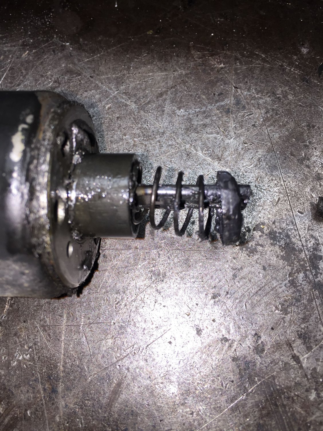
I realized the solenoid plunger pulls the drive yoke lever, not PUSHes it. The end of the yoke lever has to hook inside the open end of the plunger, against the retainer and spring. I tried several times with various long thin screwdrivers and hook tools to do just that. No good, as the plunger just pushed up into the body of the solenoid.
So...I had to pretty much completely re-disassemble the starter. This time, I installed the end of the drive yoke lever inside the rectangular hole in the plunger, against the retainer and spring. Reinstalled the armature and drive yoke lever with solenoid attached. That took a little juggling. I seated the casing, then finished installing the solenoid. Repeat assembly of everything else.
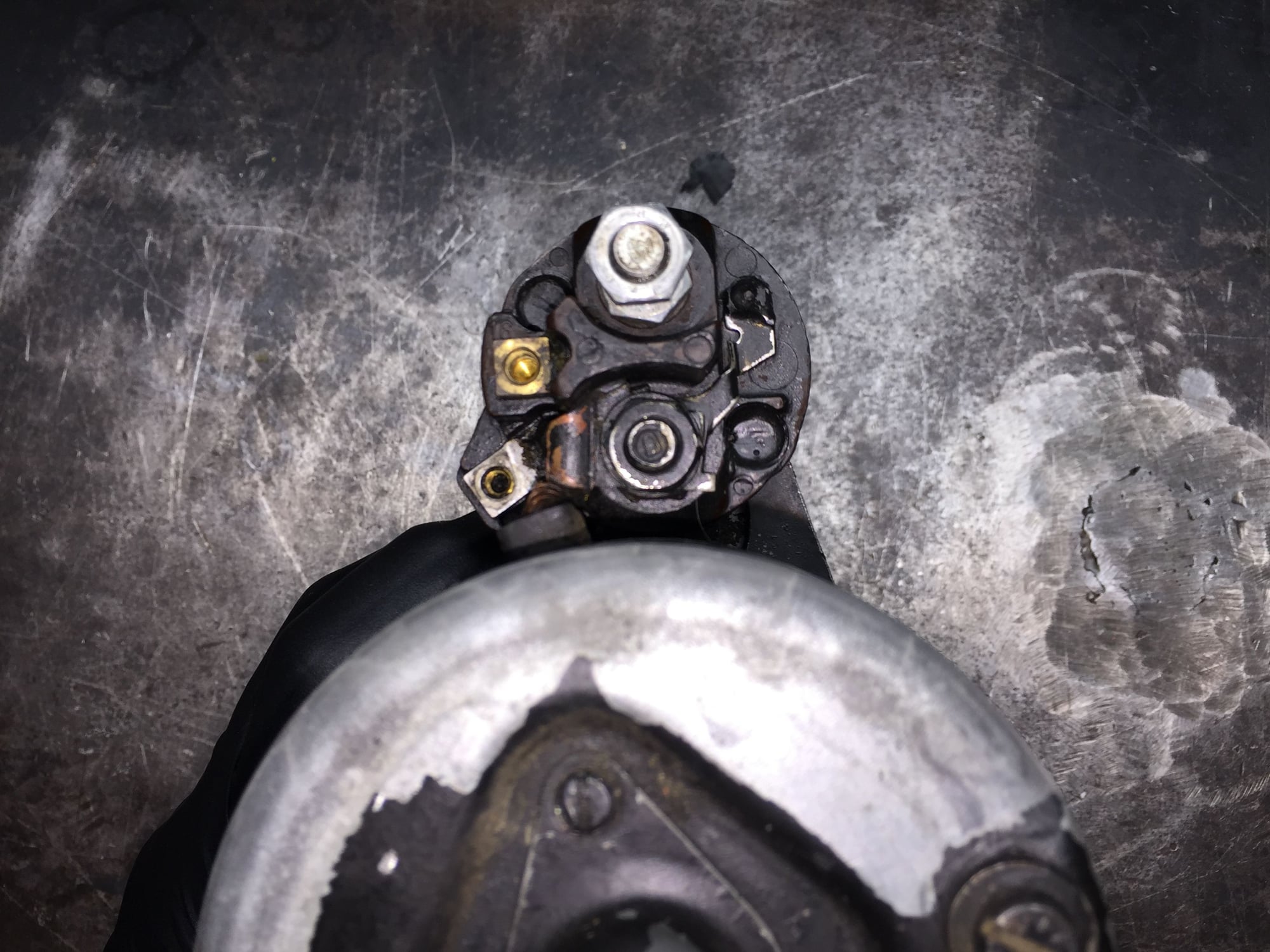
I fitted new M4 and M5 bolts and washers into the starter terminal and auxiliary hot terminal on the solenoid. I will fit toothed lockwashers at home.
Now, my intent is to chuck the starter up in a vise with a charged 12VDC battery, jumper cables, remote starter switch, Fluke clampmeter, Fluke DMM, wiring diagrams, and do some testing. I want to verify the starter operates properly. I want to see how much current it pulls free spinning, and I want to see the voltage drop across the solenoid contacts.
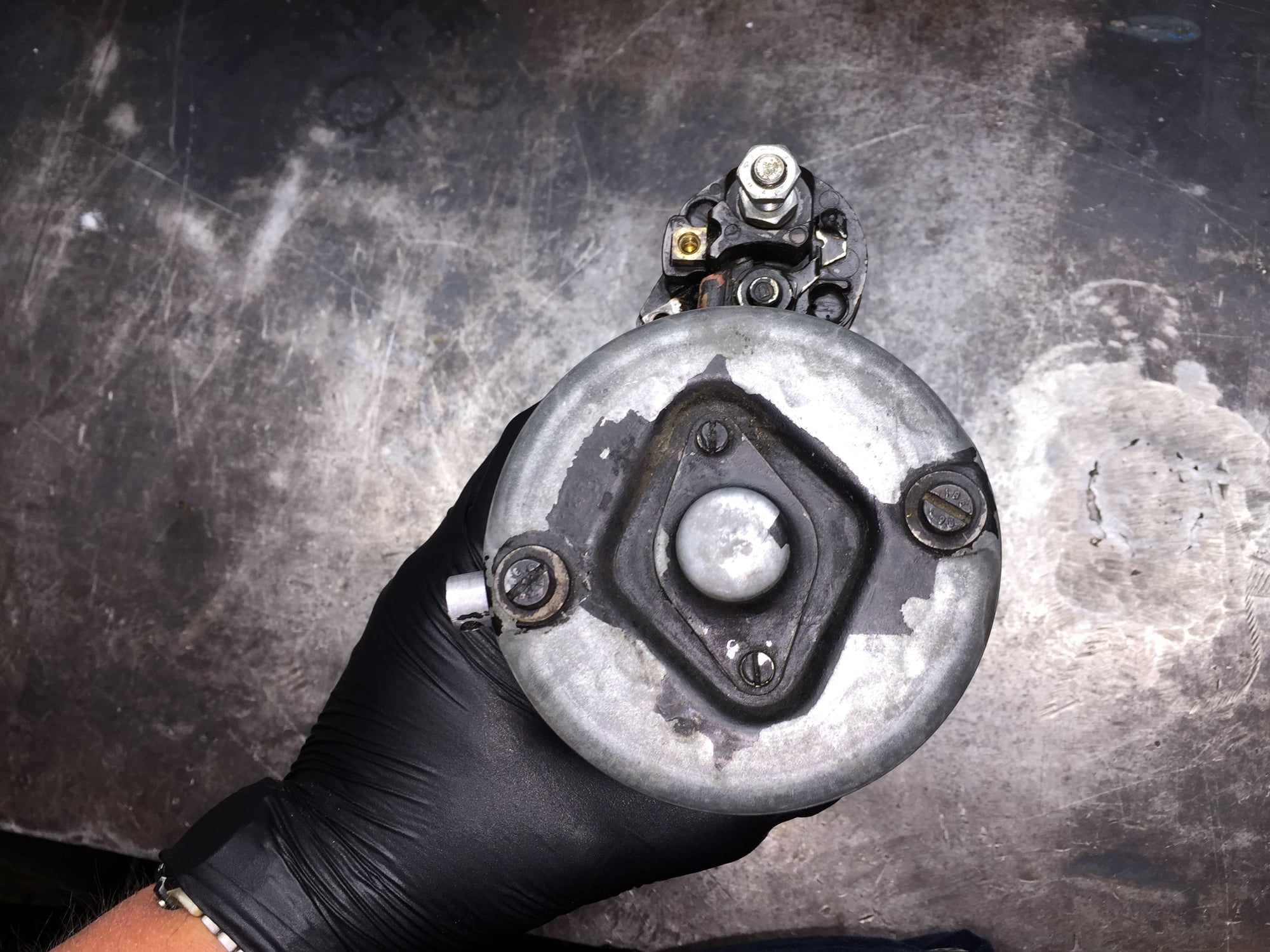
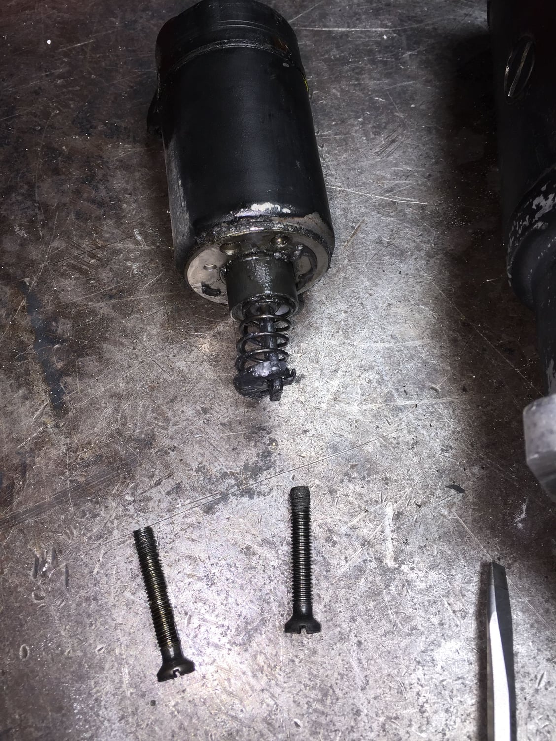
Note the end of the drive yoke lever...it should be engaged with the end of the solenoid plunger.
Manually moving the drive yoke lever.
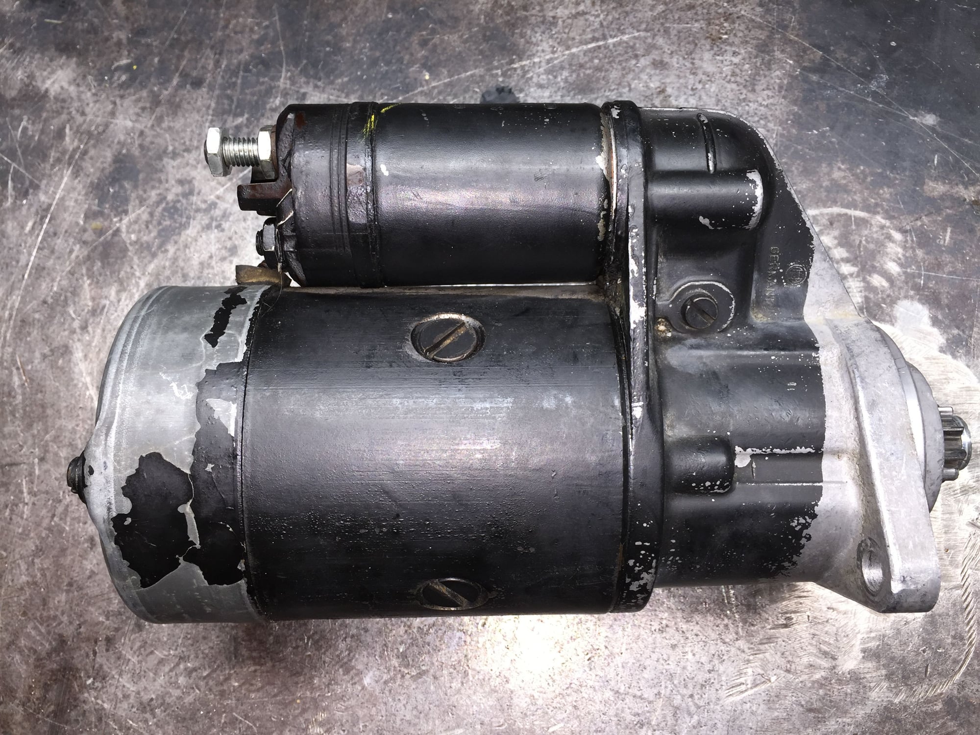
Starter back together, ready for testing. Note that I used a nylon lock nut in place of the flat nut and lock washer for the drive yoke lever pivot bolt.
Note the new M4 and M5 hardware in the start and auxiliary hot terminals on the solenoid.
In July, when I install the new (+) battery cable, I will install this starter. Then, repeat the above process on the removed starter. This way I will have a known good spare starter on the shelf.

 06-10-2016, 04:02 AM


 The end of the yoke lever has to hook inside the open end of the plunger, against the retainer and spring. I tried several times with various long thin screwdrivers and hook tools to do just that. No good, as the plunger just pushed up into the body of the solenoid.