

Defeating the Bulb Control Module
 12-10-2006, 03:53 PM
#1
Drifting
Thread Starter

Anyone defeat portions of the bulb control module? I've been wanting to defeat the third brake light so I can replace it with an LED.
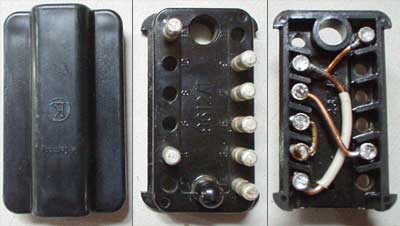
I've got a spare bulb control module (p/n 928.641.603.07). Took off the cover.
Looks pretty simple. Automotive application IC's. Found a datasheet on a similar bulb control IC. Here's the photo of the circuit board:

http://img235.imageshack.us/img235/3...trol003so6.jpg
I pasted the inverted solder side next to the component side. You can see the sheet metal shunt resistors. The circuit basically measures the voltage drop, in milivolts, across these shunt resistors. The shunt resistors are in series with the incandesant bulbs. Marker and brake lights are the only bulbs that are monitored by this unit.
borland
90' S4
I've got a spare bulb control module (p/n 928.641.603.07). Took off the cover.
Looks pretty simple. Automotive application IC's. Found a datasheet on a similar bulb control IC. Here's the photo of the circuit board:
http://img235.imageshack.us/img235/3...trol003so6.jpg
I pasted the inverted solder side next to the component side. You can see the sheet metal shunt resistors. The circuit basically measures the voltage drop, in milivolts, across these shunt resistors. The shunt resistors are in series with the incandesant bulbs. Marker and brake lights are the only bulbs that are monitored by this unit.
borland
90' S4
Last edited by borland; 06-07-2009 at 01:05 AM.
 12-10-2006, 04:53 PM
#2
Addict
Rennlist Member
Rennlist Member
Join Date: Jul 2002
Location: Edmonton, Ab
Posts: 2,286
Likes: 0
Received 0 Likes
on
0 Posts
Perfect......... I was looking for this info, and no I don't have to rip my unit apart! Thanks!
I'm looking for a way to jumper this thing out of the harness. I'll post the successful result...... maybe!
I'm looking for a way to jumper this thing out of the harness. I'll post the successful result...... maybe!
12-10-2006, 07:27 PM
#3
Drifting
Thread Starter
I was thinking about altering the circuit to allow the lower current LED while still keeping the other lamp monitoring.
But for full defeat.... There are only two outputs from the bulb control module to the instrument cluster warning lamps:
- Black wire, pin 7 (Output - Stop Light Failure)
- Red/White wire, pin 10 (Output - Marker Light Failure)
- Brown wire, pin 9 (Ground)
To disable both warnings, try rewiring the harness connector at the bulb control module, by disconnecting the two output wires leading to the bulb control module and connecting both of them to ground.
You might want to do this through a 5K resistor and measure the current first. Might not need the resistor but might be safe to check first.
12-10-2006, 07:44 PM
#4
Inventor
Rennlist Member
Rennlist Member
I deleted my central warning and bulb check brains on the '81. For the taillights, I made a jumper. BTW, there was a factory jumper like this for testing, or I suppose, for cars without the central warning option.
This connector is found on 80's Mercedes (easily found in the U-pull junkyards), a 12 pin I got from under the dash, on the passenger side. The pins are soldered so it is easy to rewire these. (Made the lights a bit brighter too?) Note that different years had different brains, so check your wiring diagrams! (This is for 81)
This connector is found on 80's Mercedes (easily found in the U-pull junkyards), a 12 pin I got from under the dash, on the passenger side. The pins are soldered so it is easy to rewire these. (Made the lights a bit brighter too?) Note that different years had different brains, so check your wiring diagrams! (This is for 81)
12-11-2006, 11:50 AM
#6
Drifting
Thread Starter
I believe Porken's plug is a replacement for the bulb control module.
So you could do a similar thing of bypassing the module with a replacement plug that connects the pins with the shunt resistors mentioned above.
Not sure how the instrument cluster handles the warning signal. Analog or Digital cluster (89'+) may provide a warning lamp driver circuit.
If the instrument cluster warning bulbs are driven directly by the bulb control module, then connecting the warning (output) wires to ground is unnecessary. Have to look at this further.
12-11-2006, 11:52 PM
#7
Owns the Streets
Needs Camber
Lifetime Rennlist
Member
Needs Camber
Lifetime Rennlist
Member
Thought the warning unit measured side to side variations.
On my 88 S4, been staring at the 'Stop' light warning after swapping in a pair of 1157 LED's on the cluster brake lights.
Just for kicks I placed an incandescent bulb back into the driver's side cluster. So there's now left and 3rd light with incandescent bulbs. LED in right cluster.
And of course the 'Stop' brake bulb warning goes out after I tap the brakes. Baffled.
I looked at the 3rd brake bulb. It's a high power bulb. Haven't found any LED that's even close to that output so I'm leaving the single pole bulb in (25W). For now.
(Got a 3W LED replacement in a Mag-Lite 3 D cell flashlight. Boy is that bulb blindingly bright. 2nd or 3rd gen Diode)
Ernest (NYC) All sorts of warning lights.
Trending Topics
12-19-2006, 12:32 AM
#8
Addict
Rennlist Member
Rennlist Member
borland, did you ever get anywhere on this?
I'm just about finished with an LED upgrade (finally getting good results with 3W Luxeon-based bulbs for all the bright stuff; I think LEDs are finally viable) and it's time to get this module figured out.
If I have time, I might try reverse engineering the bulb control module. I don't want to remove mine for any length of time, so your photos are a good starting point. Pretty basic analog electronics there (primitive stuff is actually good here!), but there's a lot of stuff I can't make out. A better photo of the component side would help (can't quite make out the resistor color codes) and maybe a list of the rest of the parts that can't be made out on the photo (e.g., I see capacitors, 4 transistors, a few zener diodes, and some common diode/rectifiers (probably).
There might actually be a pretty simple solution to keeping the unit functional, by adjusting those big shunt resistors, but I'd like to get a better idea of what's going on in the entire circuit. I'm going to start digging into my schematics for my '90 S4 tonight and see if I can get a better handle on this.
12-19-2006, 01:40 AM
#9
Drifting
Thread Starter
Ed,
I'm still working on it, as time allows. Since I just wanted to modify the circuit for one LED brake light, I was only going to draw up a partial schematic of the circuit.
For full defeat, that should be rather easy. Like I said, there are only two outputs coming from the bulb control module, as the module only monitors brake and marker lights. Just need to take a few voltage measurement to see how the instrument cluster warning lights are activated (high or low).
The module utilizes three specialized automotive application ICs, in two varieties. They are Telefunken U478B and U477B. I couldn't find the datasheets for these, but did find a similar (same functionality and pinouts) IC. Can't remember the web site I downloaded this from, but I'll send you a copy of the pdf file by e-mail.
Like you see, the discretes are all common, some with high tolerance. I can send full resolution photos too.
12-19-2006, 09:28 AM
#10
Nordschleife Master
Join Date: Dec 2004
Location: Guelph, Ontario, Canada
Posts: 6,164
Likes: 0
Received 5 Likes
on
5 Posts
Looked at this quickly. It is the same method I use with my window controller to monitor the motor load. If someone wants to reverse engineer this (the function) I will build a micro controlled version which will be able to 'learn' the load pattern of the bulb to determine if it is burnt out or not and emulate the signal to the dash. IE press a learn button while stepping on the brakes and will monitor the load, if it drops below x percent it indicates bulb failure.
Let me know if anyone is interested in doing this.
Let me know if anyone is interested in doing this.
12-22-2006, 02:10 AM
#11
Drifting
Thread Starter
Here's what I figured out... Datasheet says " Without supply voltage or open input pin 8, the output is turned off". So to defeat the warning signals, cutting the trace for each pin 8 of the three ICs, will do the trick.
Here's an anotated photo of the traces to cut..

http://img221.imageshack.us/img221/7...disableby6.jpg
This approach makes for an easy restoration the module function, by simply repairing the traces or replacing the module. And this is much simpler than rewiring the harness or making a special plug.
I've also worked out the details for defeating only the third brake light, while keeping other incandesant brake light bulb monitoring. After making these changes on my 90' S4, I'll post the results here.
Here's an anotated photo of the traces to cut..
http://img221.imageshack.us/img221/7...disableby6.jpg
This approach makes for an easy restoration the module function, by simply repairing the traces or replacing the module. And this is much simpler than rewiring the harness or making a special plug.
I've also worked out the details for defeating only the third brake light, while keeping other incandesant brake light bulb monitoring. After making these changes on my 90' S4, I'll post the results here.
Last edited by borland; 06-07-2009 at 01:06 AM.
 ... more pins on one of them.
12-22-2006, 03:29 PM
... more pins on one of them.
12-22-2006, 03:29 PM
#13
Three Wheelin'
Ed- the company that you got the LEDs from, looks like they have something you can install inline to make the load look like a regular incandescant. Not that useful if you've replace *all* the bulbs, but I"m thinking of just doing it for the 3rd brake and perhaps the actual brake lights. And they can have it replicate a 25W load, so Earnest that might work for your situation as well.
I've read that driving with your headlights on decreases fuel economy very, very slightly. Would replacing all the lights that you possibly could with LEDs possibly make a difference that you'd get slightly better fuel economy when you are driving with the lights on? Probably not enough to make up for the cost of replacing all those bulbs, but just another albeit small reason to do it.
I've read that driving with your headlights on decreases fuel economy very, very slightly. Would replacing all the lights that you possibly could with LEDs possibly make a difference that you'd get slightly better fuel economy when you are driving with the lights on? Probably not enough to make up for the cost of replacing all those bulbs, but just another albeit small reason to do it.
12-22-2006, 04:52 PM
#14
Owns the Streets
Needs Camber
Lifetime Rennlist
Member
Needs Camber
Lifetime Rennlist
Member
With the 3W Luxeons, think we're only saving 2W per bulb. If the current draw of incandescent is on par with the energy dissapation of the LED.
The chunk O' aluminum behind my 3W LED is the heat sink.
Replaced the front parking bulbs with LED and I got the hyper turn signal blinking syndrome. The LED places have LED specific relays to calm down the blink rate.
Haven't looked into that yet as I sorta like the manic blinking. Works well in the NYC traffic.
Sorta hate the idea of putting in more efficient light output only to appease the bulb check module with an old-fashioned load resistor. It just seem so Dark Ages.
Ernest (NYC)
LED = current cutting edge lighting tech.
Velcro = 928GTS era cutting edge attachment mechanism. (for that GTS rear panel)
12-22-2006, 05:07 PM
#15
Addict
Rennlist Member
Rennlist Member
Originally Posted by ew928
With the 3W Luxeons, think we're only saving 2W per bulb. If the current draw of incandescent is on par with the energy dissapation of the LED.
Originally Posted by ew928
Replaced the front parking bulbs with LED and I got the hyper turn signal blinking syndrome. The LED places have LED specific relays to calm down the blink rate.
Haven't looked into that yet as I sorta like the manic blinking. Works well in the NYC traffic.
Haven't looked into that yet as I sorta like the manic blinking. Works well in the NYC traffic.
Originally Posted by ew928
Sorta hate the idea of putting in more efficient light output only to appease the bulb check module with an old-fashioned load resistor. It just seem so Dark Ages.