Porsche 993: How to Install a Supercharger Kit
The most cost-effective way to increase horsepower is by installing a forced induction system. For the Porsche 993, a positive displacement supercharger kit can substantially increase horsepower and torque to rival that of a turbocharged car.
This article applies to the Porsche 993 (1993-1998).
For individuals looking to boost the performance of their Porsche 993, a supercharger kit is the best bang for the buck. Depending on the setup, a supercharger kit can yield an additional 100-150 horsepower over the stock engine configuration while still retaining everyday driveability. Unlike a turbocharged engine, a supercharger is very responsive and does not suffer from lag. Supercharging your 993 involves the installation of bolt-on parts that require no internal engine modifications. Additionally, your car can be returned to its stock configuration at anytime if necessary. So, if you are looking for a substantial performance boost for your naturally aspirated 993, a supercharger kit may just be the ticket. The following article details the installation of a TPC Supercharger kit for the 993 model.

Materials Needed
- Metric combination wrench set
- Metric socket set
- Ratchets and extensions
- Torque wrench
- Metric Allen wrench set
- Floor jack
- Specialty wrench or equivalent (Crank pulley removal)
- Noid light
- Soldering iron
- Drill and drill bits
Note
1996+ 993 models require the following parts for installation: Throttle Body (Part # 993 110 128 11) & Rubber Hose (993 110 367 04).
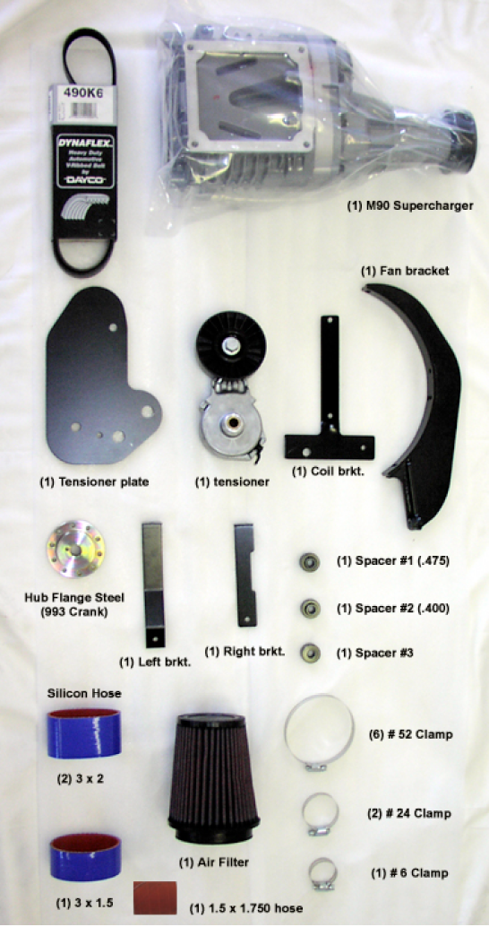
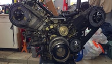
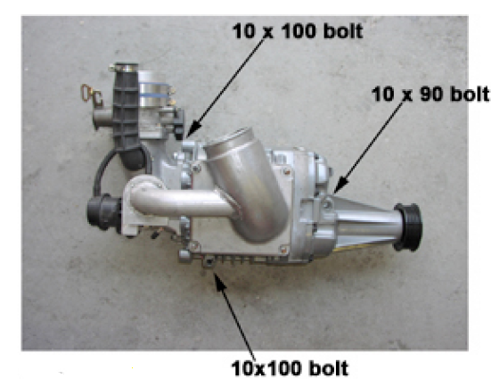
Figure 1. 993/964 Supercharger components. 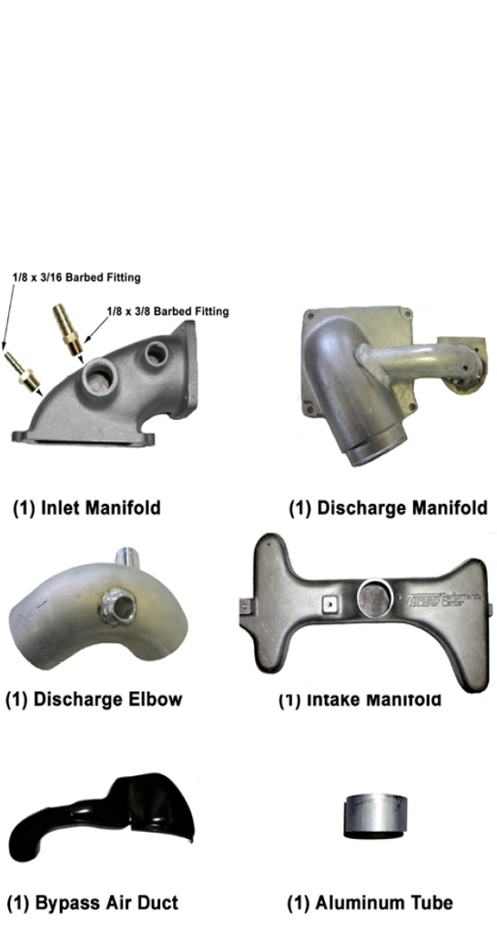
Figure 2. 993/964 Supercharger components.
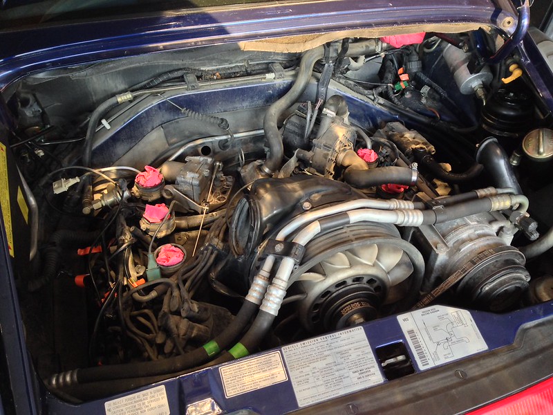
Step 1 – Remove intake manifold
- Remove the airbox assembly and intake manifold assembly. This involves removing the mass airflow sensor, accelerator and cruise control cables, and fuel vapor and brake booster lines. Inspect the velocity stacks and rubber manifold couplers. If cracked, replace as necessary. For the airbox removal procedure, see the related article:
(Related Article: Porsche 993: How to Replace Fuel Filter - Rennlist.com)
- Install left hold down bracket (See Figure 1) to the cooling shroud hold-down using the provided 6mm stud.
- Using the same procedure, install the right hold-down bracket. Be sure the bottom of this bracket sits flush upon the power steering pump bracket. Minor trimming of the hold-down bracket may be necessary depending on vehicle model year.
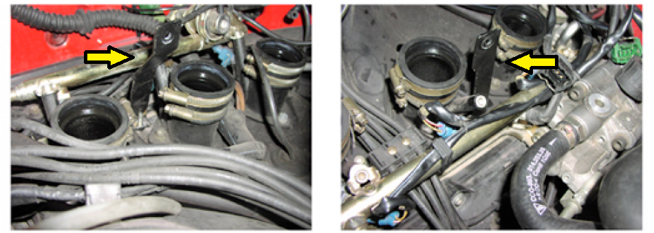
Figure 4. Installation of hold-down brackets.
Pro Tip
It is recommended that wiring and hose connections be labeled as they are removed from the intake manifold. This will assist you during reassembly.
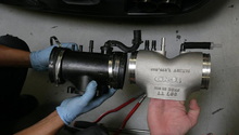
Step 2 – Relocate secondary air injection pump (SAI)
- The secondary air injection pump needs to be relocated to the right rear of the engine bay to make room for the new intake manifold.
- Remove the SAI pump from its bracket. Be sure to re-install the 6mm fastener back onto the oil pressure switch housing.
- Relocate SAI pump to the right rear shock tower mount. Reroute the pump hoses as shown in Figure 6. Minor shortening of the discharge hose may be required.
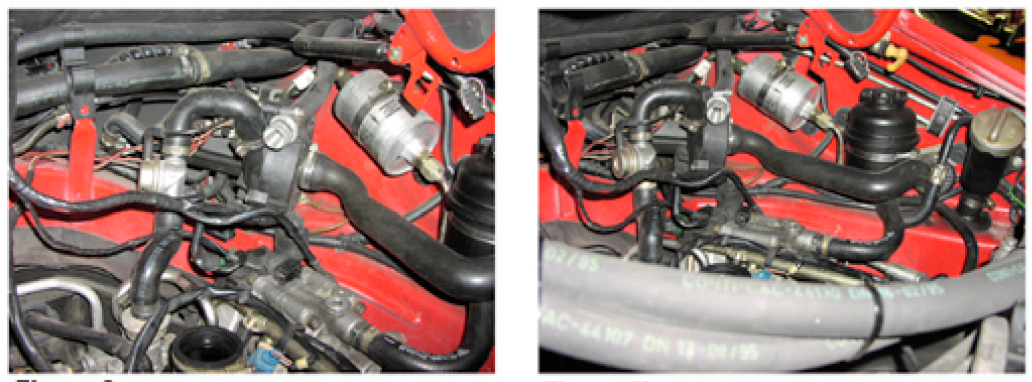
Figure 6. Relocation of SAI Pump.

Step 3 – Install new intake manifold
- Install new intake manifold into rubber couplers on the velocity stacks. Make sure the hose clamps are loose and press down evenly on both sides of the manifold until manifold bottoms out. Applying a bit of grease or oil in the couplers can aid manifold installation.
- Shift the hardline fitting at the air conditioning compressor to clear manifold if necessary.
- Tighten all hose clamps at the rubber couplers.

Figure 7. New intake manifold installed.
Step 4 – Install duct and fan bracket
- Install the bypass air duct between the cooling shroud and heat exchanger.
- Install the fan bracket to the fan housing using (3) 6mm bolts. The nose of the supercharger rests on this bracket, so it is imperative that the bracket rests properly on the factory fan housing. Trim the factory plastic cooling shroud to ensure proper footing of the new fan bracket. Overlap of the fiberglass air duct is normal.
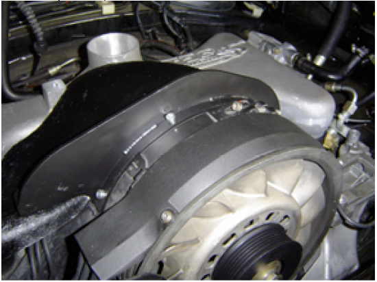
Figure 8. Fan bracket and bypass air duct installed.
Step 5 – Install throttle cable stop
- After removing the throttle cable and grommet from the engine sheet metal, install the throttle stop to the throttle cable making sure the stop faces upward (refer to Figure 9).
- Route the throttle cable back through the engine sheet metal and install the grommet. Ensure the throttle stop is positioned behind the engine sheet metal or full throttle operation will be interrupted.
- Check throttle operation.
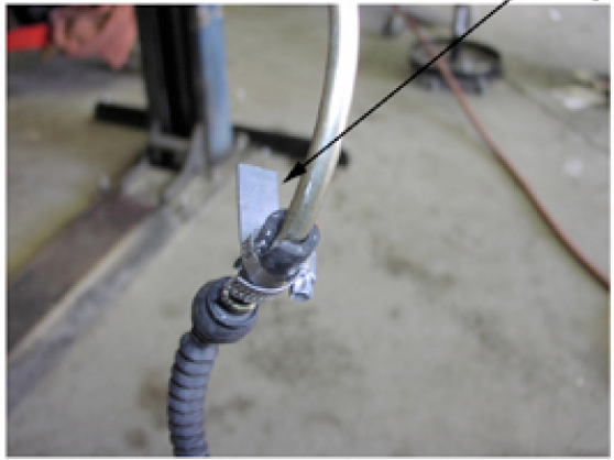
Figure 9. Throttle cable stop.
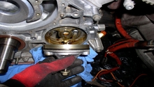
Step 6 – Install fan pulley
- Remove the factory alternator/fan pulley.
- Using the factory nut and washer, install the new provided pulley making sure to use red threadlocker on the pulley bolts.
- Remove the belt tension sensor and bypass it by jumpering the two wires together.

Figure 11. Belt tension sensor.
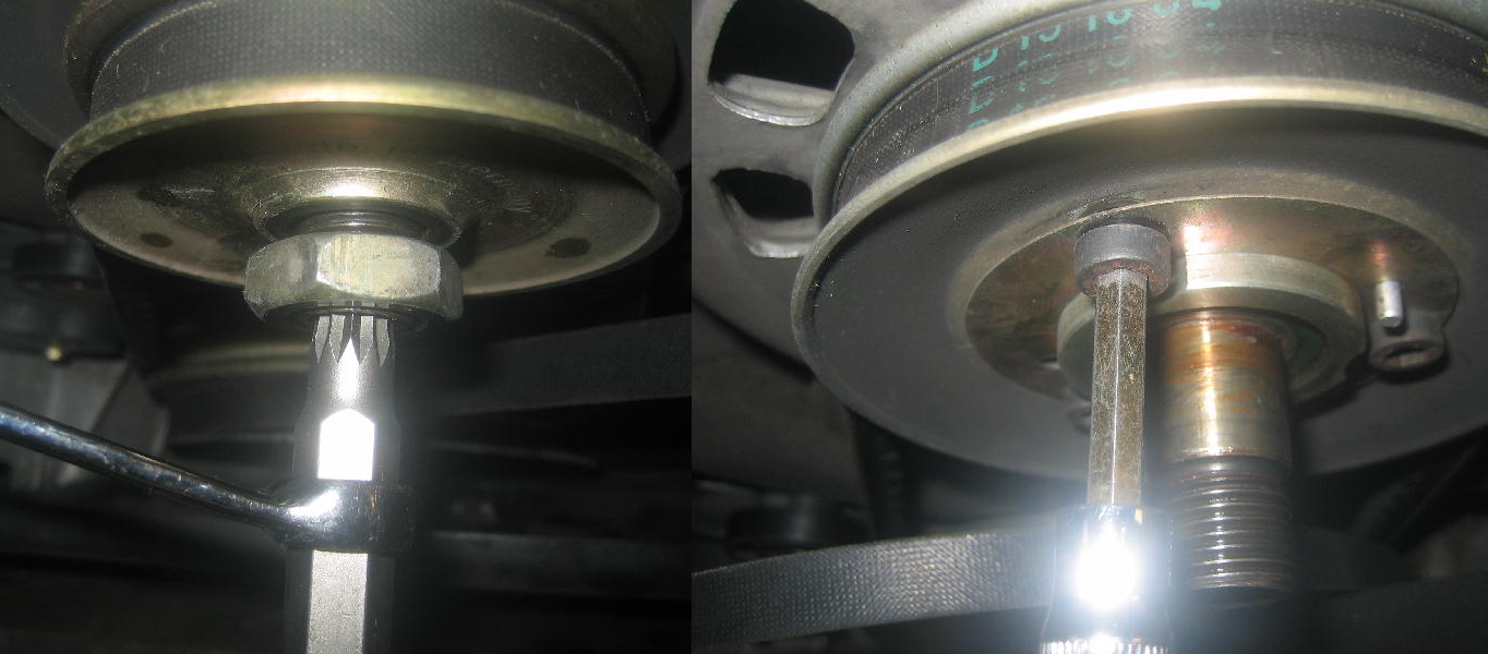
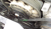
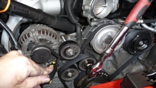
Step 7 – Change crank pulley
- To gain access to the crank pulley, the exhaust system must be removed. For 993s, the catalytic converters, cross-over heat exchanger pipes, and mufflers must be removed.
- Support the engine with a floor jack and remove the engine support bracket. Slightly lower the engine for easier access to the crank pulley.
- Remove the crank pulley bolt and remove old crank pulley from engine.
- Install new crank pulley and hub flange. Secure hub flange to crank pulley with (3) 6mm bolts. Use red threadlocked when installing both crank pulley and hub flange.
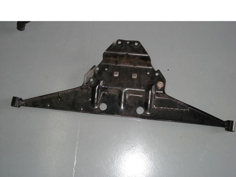
Figure 12. Engine support bracket. 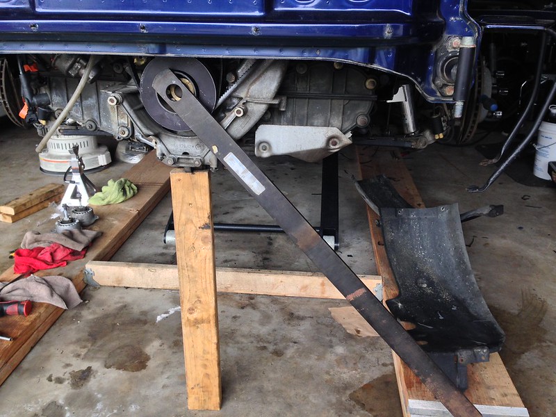
Figure 13. Crank pulley removal.
Step 8 – Install tensioner plate
- Using the supplied template, drill holes in the engine support bracket.
- Install tensioner plate and coil bracket (993 only) to the engine support bracket. If your engine support bracket does not have factory reinforced welds, use supplied alignment shims and spacers when mounting the tensioner plate.
- The engine support bracket and exhaust can now be reinstalled.

Figure 14. Engine support bracket with new accessories mounted.
Step 9 – Assemble and install supercharger assembly
- Install inlet manifold to supercharger using (2) 8mm x 1.25 studs and nuts. Seal with Loctite 518.
- Attach the compressor bypass valve to outlet manifold using 6mm bolts. Seal with Loctite 518.
- Mount supercharger using supplied 8mm nuts and stud. Then install the 10mm hold-down bolts to secure the supercharger to the engine. (See Figure 15 for orientation). For 96+ models, route air conditioning lines as shown in Figure 16 prior to installing the supercharger.
- Install drive belt.
Fogure 15. Assembled supercharger. 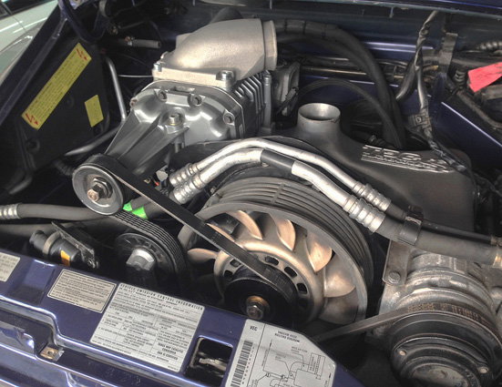
Figure 16. Supercharger installed on engine.
Step 10 – Additional assembly
- Install discharge elbow and pressure relief valve onto supercharger using supplied silicone boots and clamps.
- Install the fuel injector on the driver's side fuel rail. Remove the shrader valve from the fuel rail and install the fuel injector using the 90 degree fitting, making sure the injector is firmly seated.
- Install the mass airflow sensor, idle motor, and air filter.
- Hook up all vacuum lines (Figure 18) and throttle and cruise control cables.
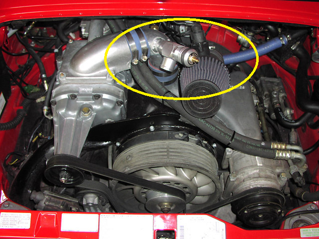
Figure 17. Remaining components installed on supercharger. 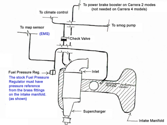
Figure 18. Vacuum hose diagram.
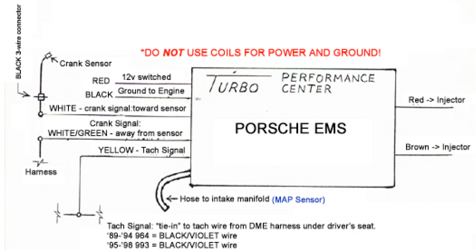
Step 11 – Install engine management system
- Mount engine management system on the fuse panel lid, located at the left rear of the engine bay.
- Wire engine management system as shown in Figure 19. It is recommended all connections be soldered.
- Test the function of the newly installed fuel injector and engine management system by attaching a noid light on the injector connector. The light should illuminate under positive manifold pressure (when supercharger is producing boost) if functioning correctly.
Warning
The car must use a stock DME chip or else engine damage can occur. Ensure your DME is using a stock chip.
Step 12 – Check operation
- Start the car check for proper drive belt alignment.
- Check for vacuum leaks.

Related Discussions
- Another TPC Supercharger Install Project - Rennlist.com
- TPC Supercharger Install Complete - Rennlist.com
- How to Remove Crank Pulley - Rennlist.com