Porsche 928: How to Program Keyless Remote
Installing a keyless entry system to your Porsche 928 is a great way to upgrade your vehicle. Most aftermarket systems are inexpensive and fairly simple to install. Here's how to do it.
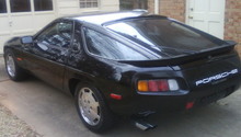
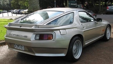
This article applies to the Porsche 928 (1979-1995).
Adding a keyless entry system to your Porsche 928 is a simple, inexpensive upgrade you can perform at home. It's also a terrific convenience to have, as you'll no longer need to fumble with your keys to find the car keys to unlock the doors. There are several different system types available, both online and in your standard brick-and-mortar auto parts store. Read on to learn how to install a keyless entry system in your 928.
Materials Needed
- Keyless entry system
- Wire cutters
- Electrical tape
Step 1 – Confirm the wiring set up of your car
Confirm everything with the wiring diagrams for your model years. There were many changes over the years—a quick Google search of your 928’s model type and year should yield results.

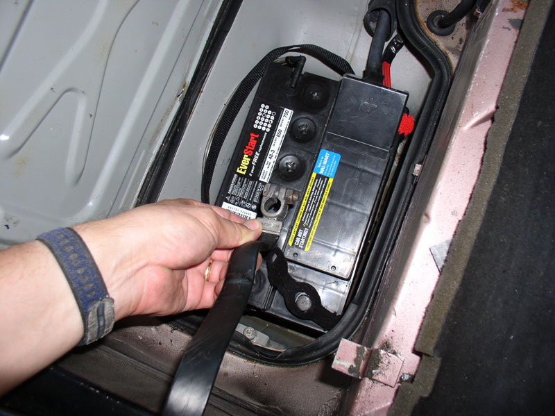
Step 2 – Disconnect the battery
Since you are installing an electrical component to your vehicle, you will need to shut the power off to the car. Disconnect the negative terminal first, followed by the positive terminal. Lay both wires away from one another so they do not cross while you are installing your system.
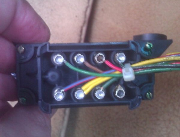
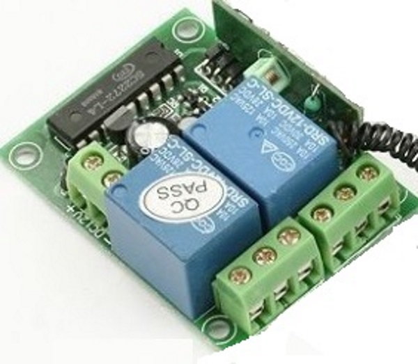
Step 3 – Install your keyless entry system
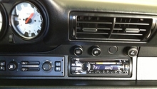
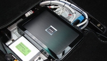
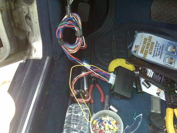
All keyless entry systems come with a guide. Follow the instructions within the guide, as they vary by brand/car type. The following is a summary of the wiring involved with your system’s receiver unit, and where to connect it in your car. Place the receiver under the driver’s seat for easy access.
For all wires that you do not use (e.g. alarm, hood pin, etc.), cut the wire and cap.
Wire Color |
Where to Connect |
|---|---|
RED (+) |
12v constant supply for control moduleTap into one of the main leads you run from the battery for the system's 6-pin connector (detailed in Step 4). |
BLACK |
Chassis grounds; You may need to drill and place a ground screw in the sheet metal below the seat. |
GREEN |
Tach/Spark pick up; Wrap wire around the #1 plug wire and join the green wire and run it along the hood, in the narrow gap between the fender and windshield, across the front door frame, and up under the front parcel tray. |
BLUE |
Hood pin switch. |
YELLOW (+) |
Side of brake switch; Splice into the brake wire at the connector on the brake switch located above brake pedal. |
WHITE |
Tap into the parking lights at the main fuse panel. |
Step 4 – Install six single pin connectors
Wire Color |
Where to Connect |
|---|---|
PURPLE |
Connect to YELLOW wire from ignition harness — this is powered only in the START position. |
ORANGE |
Connect to RED/BLACK wire from ignition harness — this is powered only in the RUN position. |
YELLOW |
Connect to BLACK wire from ignition harness — this is powered in RUN and START position. |
BROWN |
Connect to BLACK/YELLOW wire from ignition harness. |
RED (+) |
12 volts 30amp fused; Connect to battery or a constant 12v source. |
Step 5 – Install secondary connectors
Connector |
Where to Install |
|---|---|
Receiver/Antenna |
Place the antenna in the upper front corner of the rear driver side quarter glass and run the lead on the inside of the panel. |
Door / Lock (GREEN) |
Tap into the connector to the central locking module under / behind the center console area and use the GREEN WIRE (module is on the driver’s side of the radio). |
Door / Unlock (YELLOW) |
Same as above, just use the YELLOW wire. |
Status LED |
Drill hole in bottom of right side defroster channel and mount in left most defroster vent by wrapping LED with black foam for a tight fit. |
Program Switch |
You can place this under the driver seat with the rest of the receiver module. |
Step 6 – Re-connect battery and test keyless fob
Now that the wires are installed, you can re-connect the battery – positive terminal first, followed by the negative terminal. Make sure not to cross the wires.
Now that the car has power, you can test your key fob. Check to make sure the system does the most basic of things—lock/unlock the car. Also, check to see if it flashes the car lights. If, however, you need to program the fob, this would be the time to follow the manufacturer’s instructions on how to do this. NOTE: It varies by brand.
Related Discussions
- Keyless Entry and Remote Start Installation - Rennlist.com
- Installing an Aftermarket Remote Entry System - Rennlist.com
- Remote Entry Key Fob Programming Made Easy - Rennlist.com
- Keyless Entry on Early 928 - Rennlist.com
- A Few Keyless Entry and Remote Start Questions - Rennlist.com