When you click on links to various merchants on this site and make a purchase, this can result in this site earning a commission. Affiliate programs and affiliations include, but are not limited to, the eBay Partner Network.
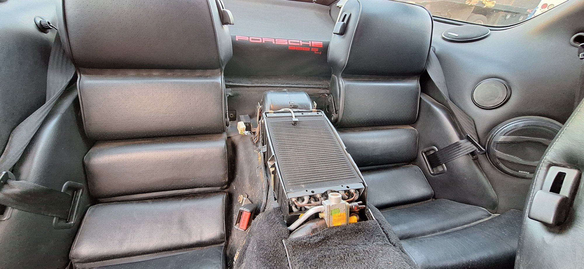
Somewhat unloved and seldom used, I have remade the rear air on my '89 auto into something that actually works for me. I thought I would share tips, tricks, and any info I have found in one place. Please add your own knowledge, as well.
I measured the amp draw of the blower at each speed, I - 1.25A, II - 2.75A, III - 4.5A
This is one of the best things I have done. The rear ac is annoying because the fan runs whether or not the compressor is running.
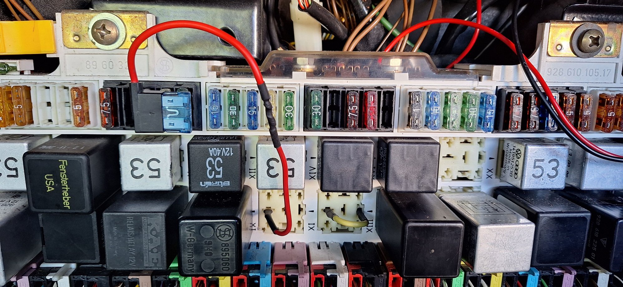
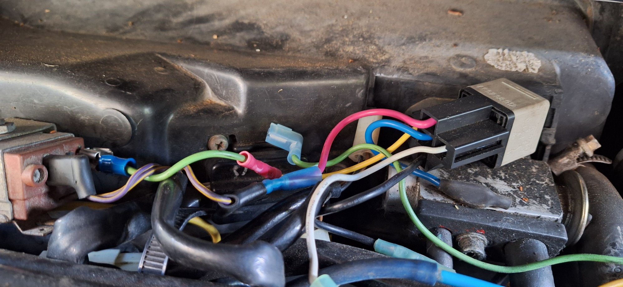
I ran a wire from the suppressor relay socket to the rear air fuse location with an Add-A-Fuse inserted upside down. Now, the rear air is switched by the AC button.
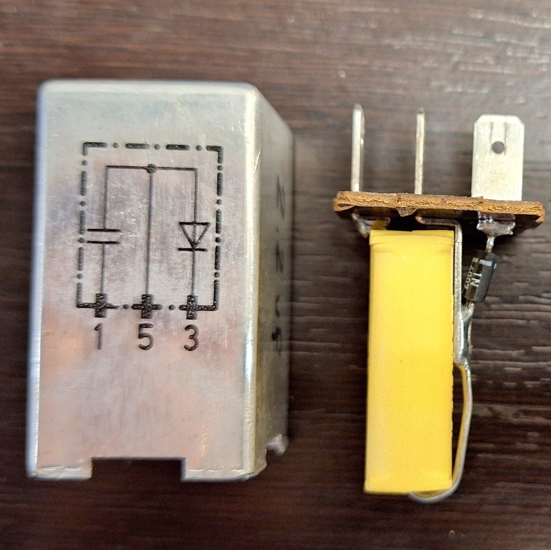
The primary Add-A-Fuse spot is left empty. I have since changed the stock blue 15A fuse to a brown 7.5A, after measuring the rear air pulls 5.8A total on high. I will replace the suppressor relay with my own 1N diode to the center terminal.
Side note: the yellow jumper above, replacing the fog light relay, turns the fog lights into DRL.
The suppressor relay dampens compressor coil feedback on shutoff. (To protect the AC head? Radio click?) It has three terminals in a row. Terminal (3) from the freeze switch goes through a diode to (5) ground and terminal (1) is interior lights +12V through a 2.2uf capacitor to (5) ground. (Radio click?)
The 1.25mm purple/yellow suppressor wire comes from the freeze switch. (Below, left.) The other purple/yellow 1.25mm wire goes through the hi/lo switch and on to the compressor. 1.25mm wire is rated for 13A.
I did not use a relay at the CE panel, although you could, mostly because the PO had installed a bypass relay at the freeze switch, which gets power through a fuse at the ABS power point near the radiator. BTW, the AC head relay got to be so bad, that it was only putting out 5V, so I found a 20/30 amp (944) relay that closes with only 5V, vs. about 9V for the 30/40 amp relays.
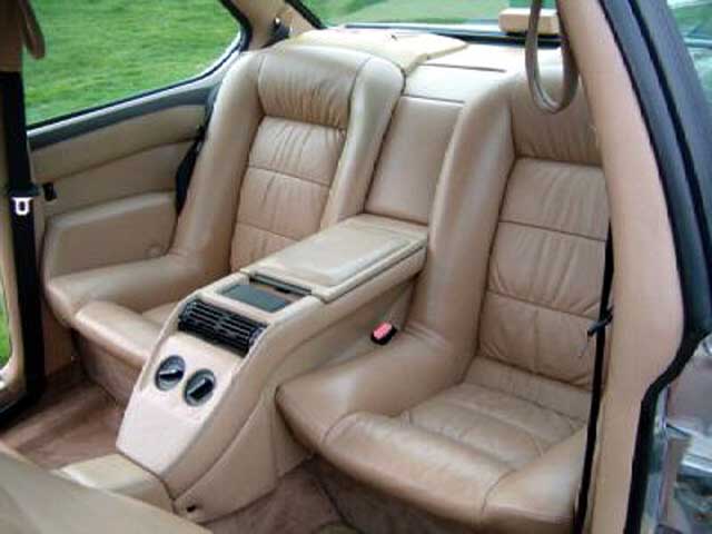
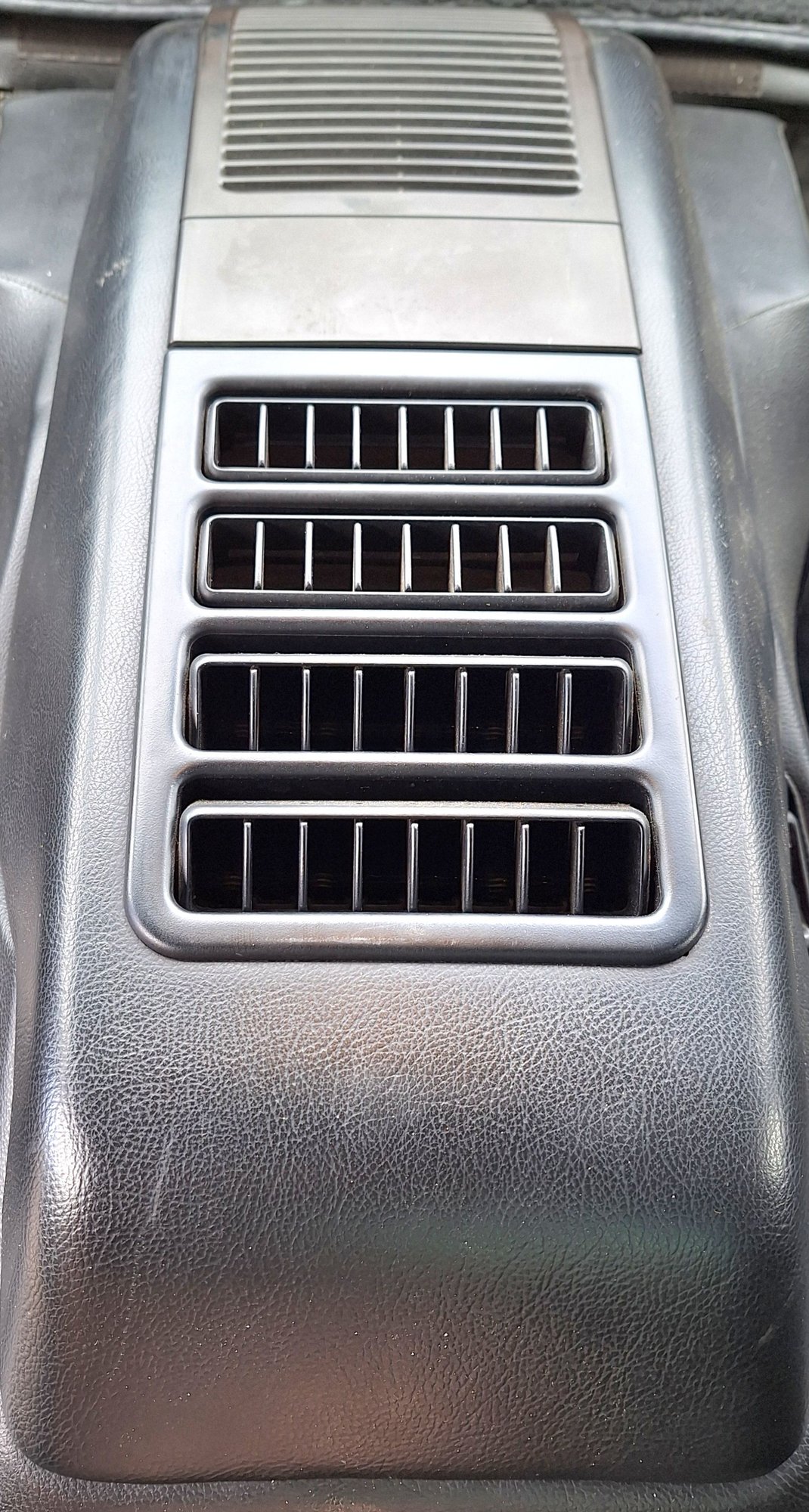
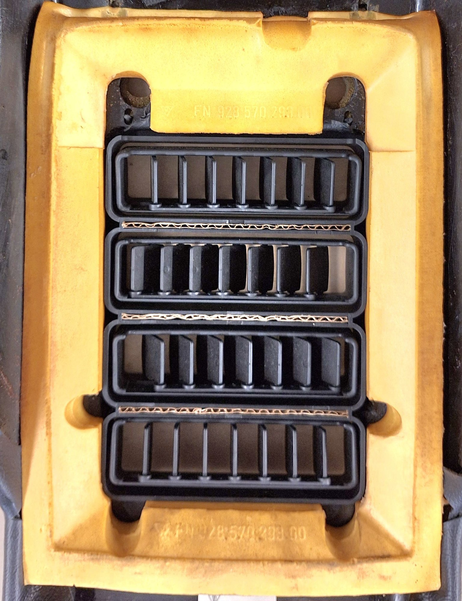
There is just too much vented area for the little blower. (Note the size of the BMW vents above.)
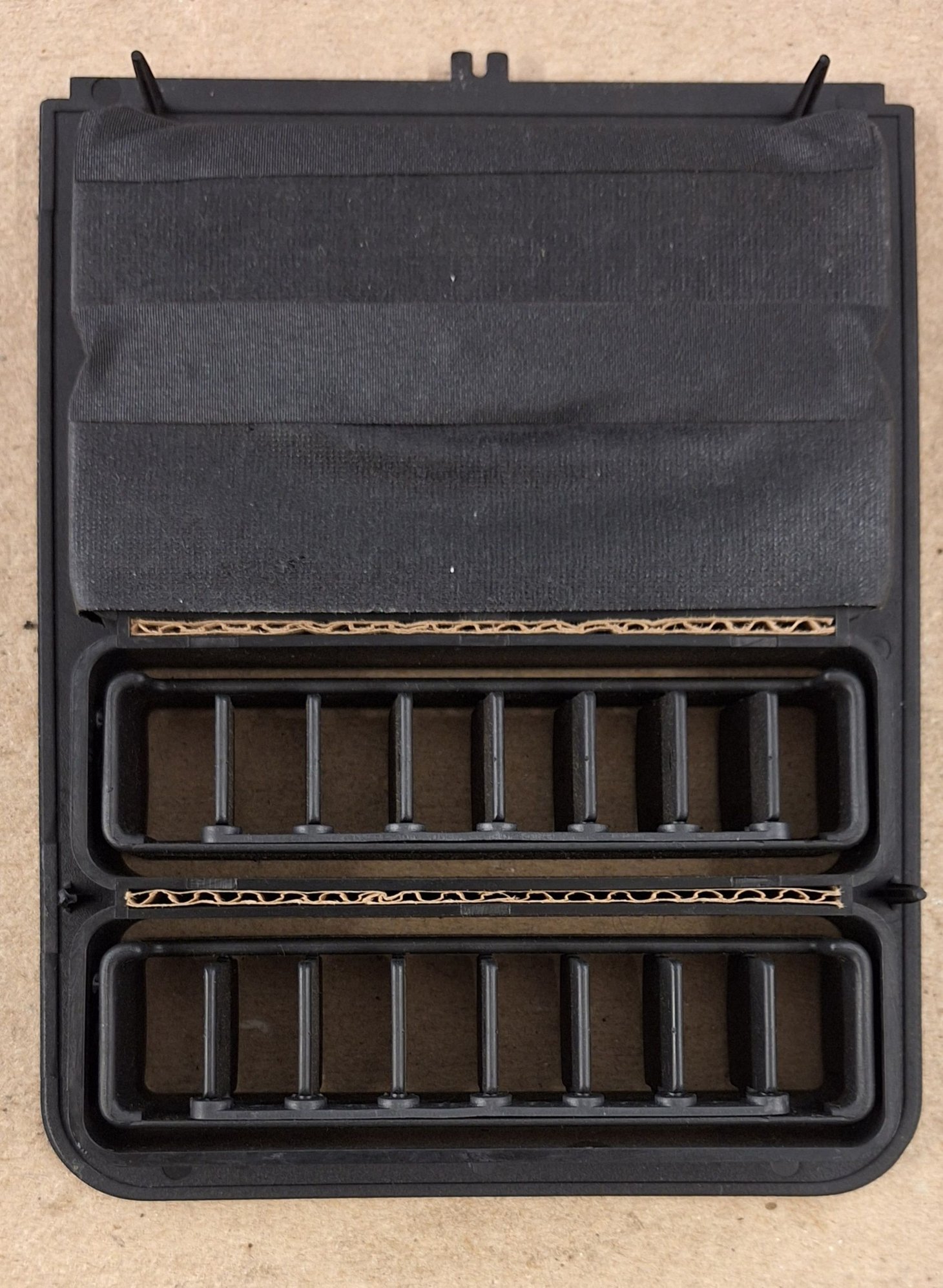
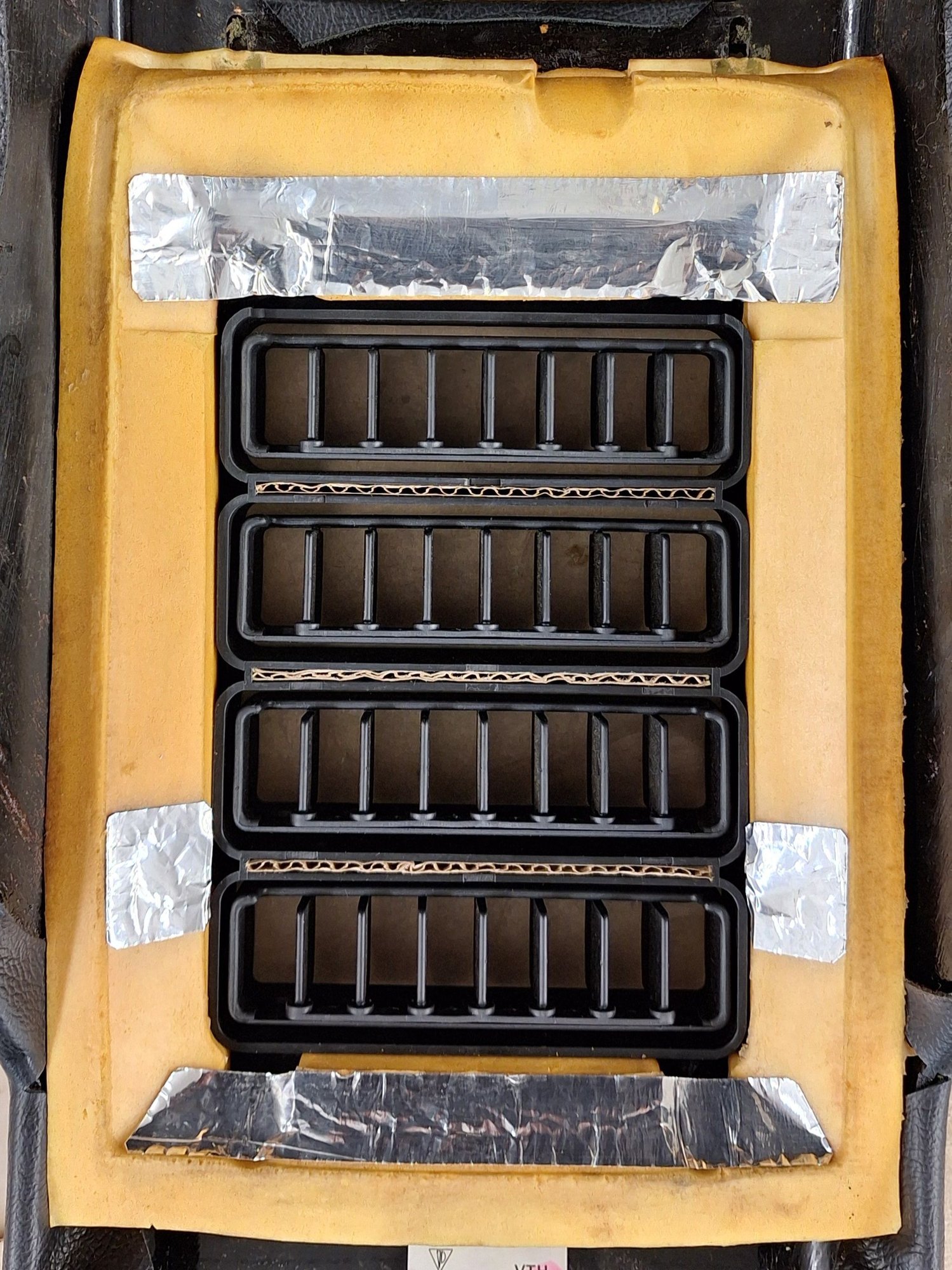
Tape over the rear two vents for a concentrated forward flow, even at the lowest fan speed. Also, fill the warped separators with cardboard.
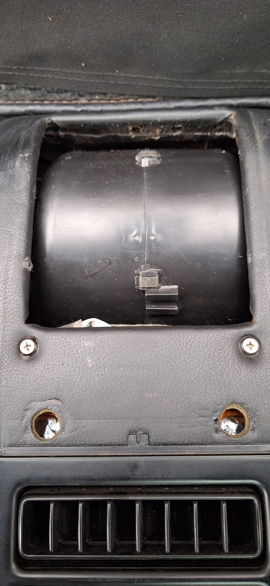
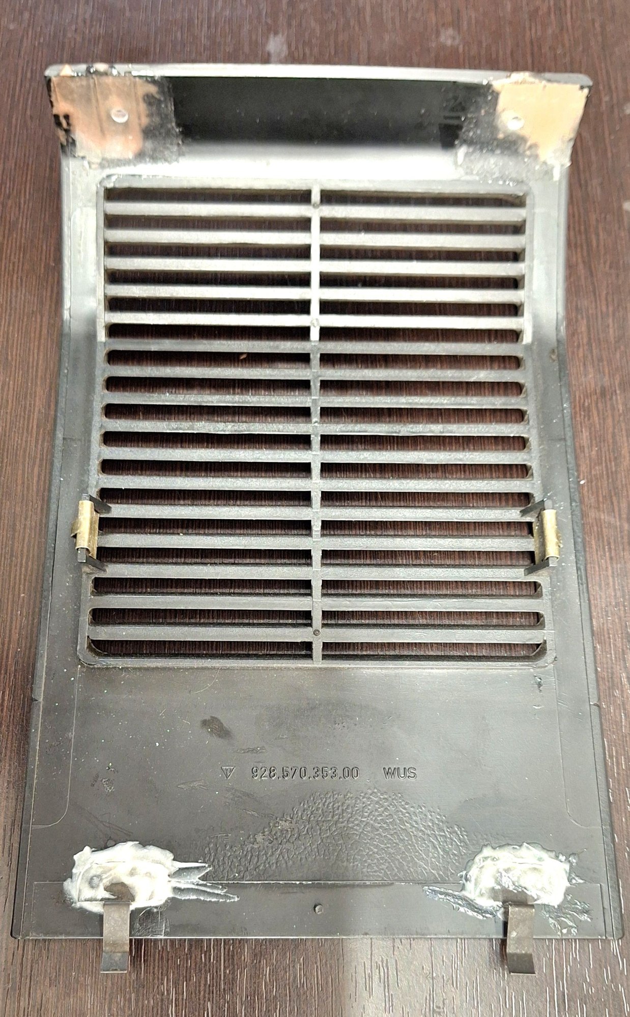
Do not try to pull out the vent assembly like this! The small plastic pins are fastened with push clips from underneath. The complete lid must be removed.
The rear intake panel must be remove first. It is held down by two small Phillips head screws at the rear. Lift rear up slightly and pull rearward to clear two front clips.
Thanks, Ken. Currently looks like I have a leak from back ac unit. This helps seeing how to begin disassembly. Still running R12, bought bunch of R12 old stock and o rings, expansion valve. Need to find shop that still services R12! Will look to mod as you are doing after recharge.
Indeed, this truly is a good idea for a thread for ignored territory. I completely refurbished my front/rear AC system last summer.
All condensor/evaporator coils should be individually flushed and vacuum tested, when TEVs are replaced. It�s not that difficult.
As regards leaks in the rear evap, it�s been long recommended to place the rear evaporator under vacuum while reinforcing the copper (brass?) tube-to-aluminum connections with JBWeld, leaving it on vacuum until the weld hardens. Of course this should be done with the rear evap on the bench.
I have no rear leaks anywhere including rear AC.
The derelict item in my rear AC is the resistor pack. It tends to often work at just the highest speed setting. However there are instances on cooler days when it works correctly at all speeds, but the fan never work �all the time� with the fan speed off, which makes sense, since the fan has a �0� off speed setting.
My 80 pound puppy loves the rear AC. I'm currently in the design stage for a rigid deck that will lay over the folded down seat backs while leaving the vents exposed for her. She'll gladly soak up all of that cool air and relieve my of the need to push it forward.
How do I get the outermost portion of the surround off of the rear AC? It's off in your first entry, and gone in entry #4. On my computer, #4 ends with "continues,.." Is there more?
Also, I'm going to start another thread now, entitled "How the heck do I get the front TEV reconnected?"
This is one of the best things I have done. The rear ac is annoying because the fan runs whether or not the compressor is running.
I ran a wire from the suppressor relay socket to the rear air fuse location with an Add-A-Fuse inserted upside down. Now, the rear air is switched by the AC button.
The primary Add-A-Fuse spot is left empty. I have since changed the stock blue 15A fuse to a brown 7.5A, after measuring the rear air pulls 5.8A total on high. I will replace the suppressor relay with my own 1N diode to the center terminal.
Side note: the yellow jumper above, replacing the fog light relay, turns the fog lights into DRL.
The suppressor relay dampens compressor coil feedback on shutoff. (To protect the AC head? Radio click?) It has three terminals in a row. Terminal (3) from the freeze switch goes through a diode to (5) ground and terminal (1) is interior lights +12V through a 2.2uf capacitor to (5) ground. (Radio click?)
The 1.25mm purple/yellow suppressor wire comes from the freeze switch. (Below, left.) The other purple/yellow 1.25mm wire goes through the hi/lo switch and on to the compressor. 1.25mm wire is rated for 13A.
I did not use a relay at the CE panel, although you could, mostly because the PO had installed a bypass relay at the freeze switch, which gets power through a fuse at the ABS power point near the radiator. BTW, the AC head relay got to be so bad, that it was only putting out 5V, so I found a 20/30 amp (944) relay that closes with only 5V, vs. about 9V for the 30/40 amp relays.
so the relay #1 slot sends power to the fan? Will that affect the interior lights?
My 80 pound puppy loves the rear AC. I'm currently in the design stage for a rigid deck that will lay over the folded down seat backs while leaving the vents exposed for her. She'll gladly soak up all of that cool air and relieve my of the need to push it forward.
How do I get the outermost portion of the surround off of the rear AC? It's off in your first entry, and gone in entry #4. On my computer, #4 ends with "continues,.." Is there more?
Also, I'm going to start another thread now, entitled "How the heck do I get the front TEV reconnected?"
Torfin
I had my rear AC completely disassembled during the AC reseal/refresh. The outmost shell must be removed by first removing both rear seats.
For the front TEV, remove the hood and may have to loosen AC pressure/suction line fasteners at the firewall in order to get some working space to fasten in a new TEV.
check Dr Bob�s suggestions in the thread below regarding front TEV access: https://rennlist.com/forums/928-foru...ion-valve.html
The derelict item in my rear AC is the resistor pack. It tends to often work at just the highest speed setting. However there are instances on cooler days when it works correctly at all speeds, but the fan never work �all the time� with the fan speed off, which makes sense, since the fan has a �0� off speed setting.
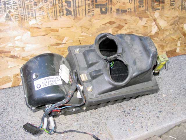
My fan was noisy and hardly blew any air. I found the squirrel cage fan was rubbing on the housing, which had warped over time. The rear blower housing can be removed without removing the evaporator. I used a small heat gun to pull the housing back into shape. Photos of this to follow.
Originally Posted by torfin
How do I get the outermost portion of the surround off of the rear AC? It's off in your first entry, and gone in entry #4. On my computer, #4 ends with "continues,.." Is there more?
There are more photos to follow. It is not too difficult to remove the lower part, but there is a trick to getting it out.
so the relay #1 slot sends power to the fan? Will that affect the interior lights?
#3 is the compressor terminal, which I am using for the fan.
Strangely, you have to go all the way up to the 90 WSM ac/heating wiring diagram to see the suppressor relay connection between the lights and terminal #1. Even then it is a cryptic redirect to [J6], which takes you to the light wiring page and shows the connection to interior light power as [H36]. (In early WSM the suppressor relay is shown on the ac/heating page as if cut in half. Terminal #1 is missing entirely. Later, #1 is shown, but not connected to anything.)
BTW, the interior light wires are only 0.5mm, so #1 is not a good place to get power if someone wanted to put in a relay for the rear air.
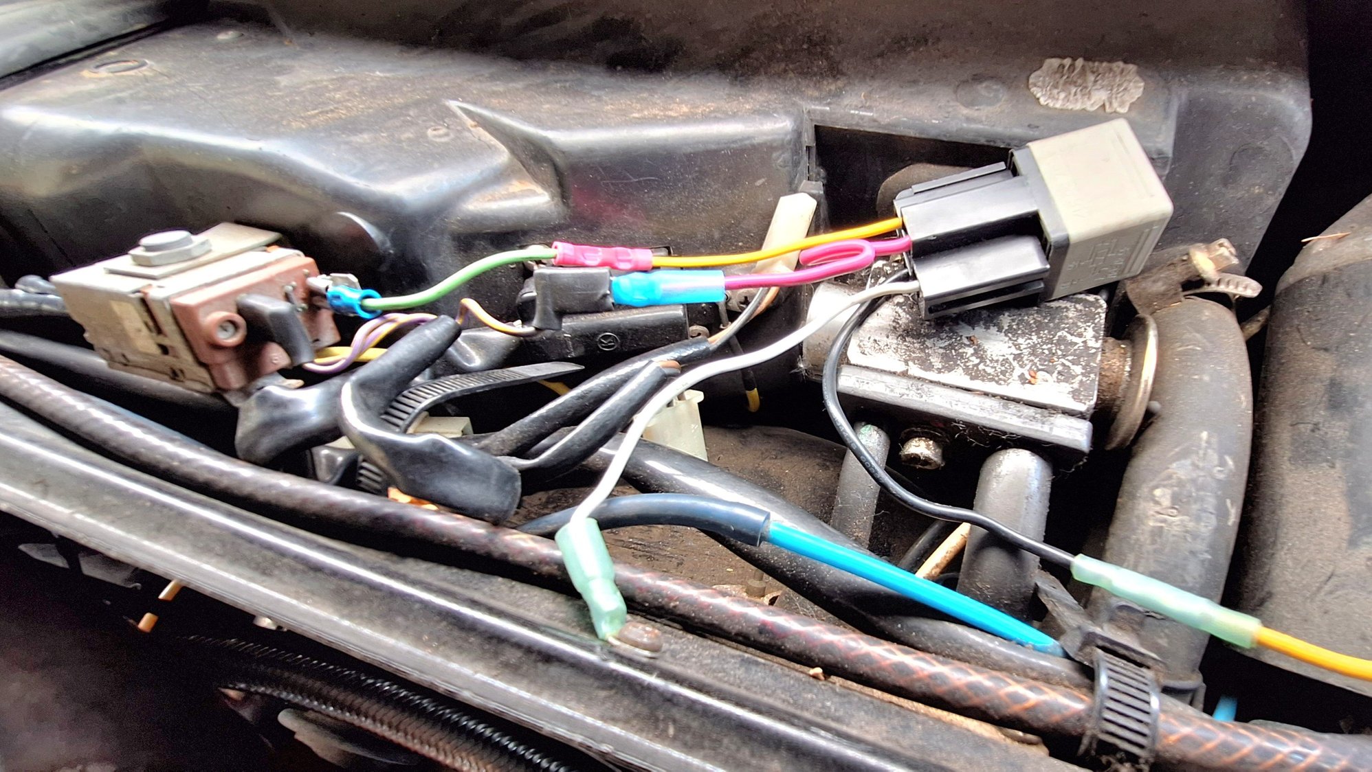
This photo above is messy, and I got the wires mixed up.
30 - black wire, power from the ABS terminal, 10A fuse
87 - red wire, connects to the single purple/yellow compressor wire
86 - yellow-crimped-to-green wire is plugged into the freeze switch
85 - white wire, relay ground to a metal screw into the firewall
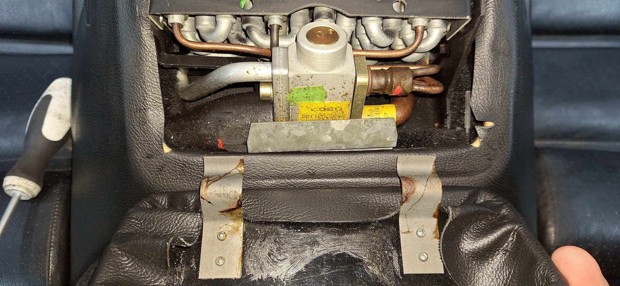
There is a add-a-terminal plug on the freeze switch input to easily bypass the switch for super cold AC if desired. (Hot dry climates.)
There are two purple/yellow wires connected to the freeze switch. The 1.25mm one is from the AC head relay. The second 0.5mm wire goes to the LH as the "AC on" input (pin 15 - not shown in WSM).
The single purple/yellow 1.25mm wire goes back to the CE panel and splits to the suppressor relay #3 terminal, to the compressor via the hi/lo pressure switch, and to the LH "compressor engaged" input (pin #14).
The ABS power terminal. 6mm Phillips head bolt under the black plastic cap.
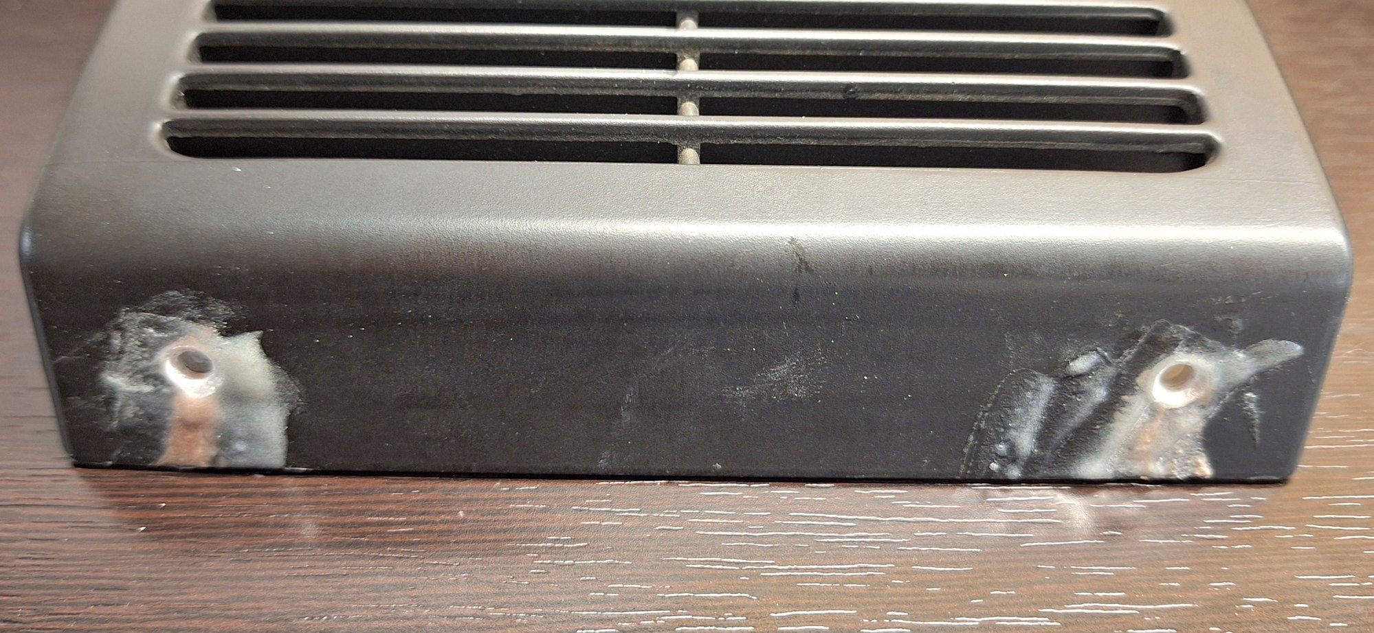
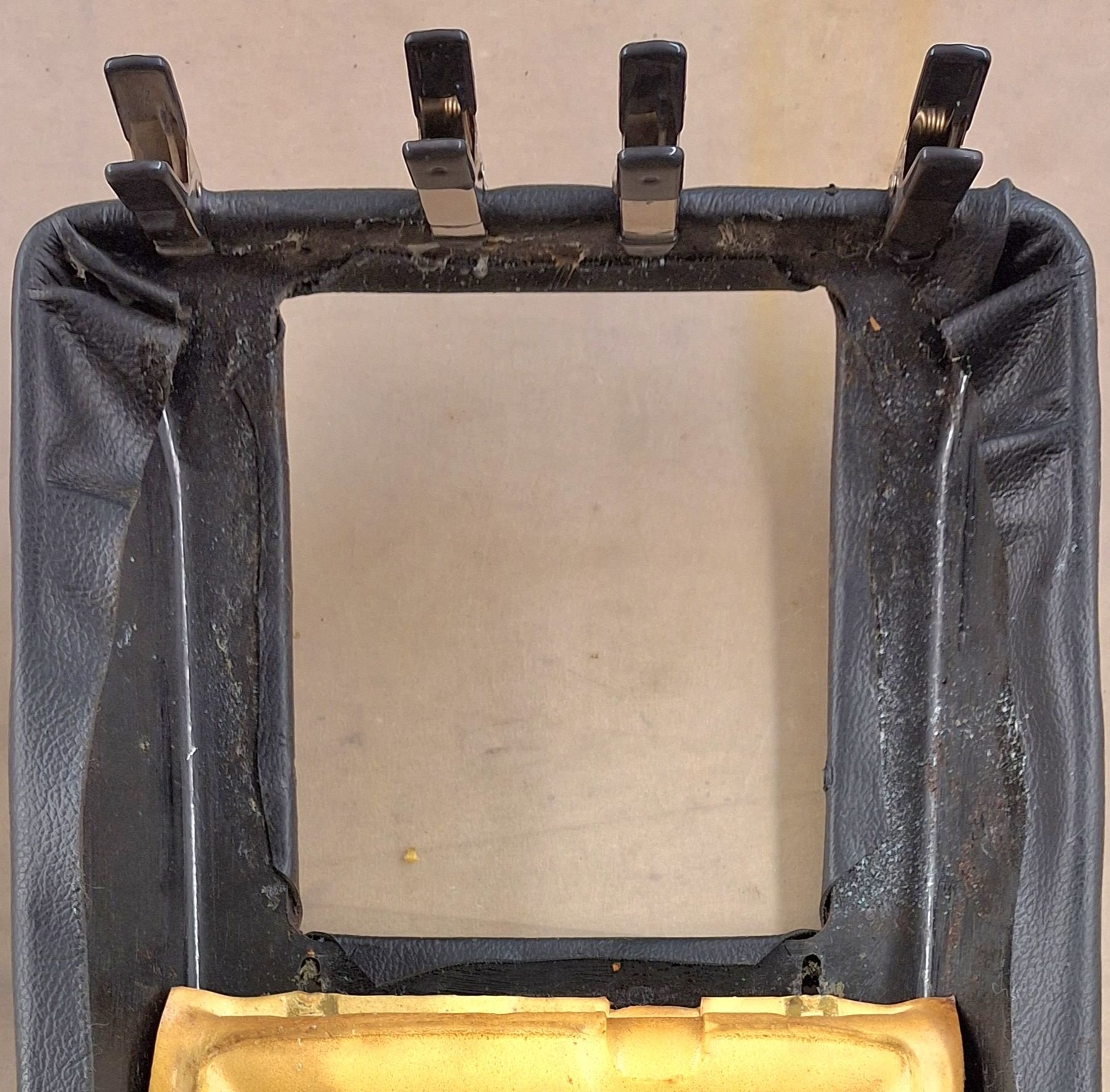
Unfortunately, your intake cover is most likely broken. The front metal hooks are only attached by some very small melted bits. The rear holes on my were cracked and the holes oversized so I had a friend rebuild them with resin and fiberglass mesh along with reattaching the front hooks. Then I redrilled the holes and chamfered them to match the screws.
Fortunately, you do not really need the front hooks. The side clips hold the cover in place pretty well by themselves.
... I will replace the suppressor relay with my own 1N diode to the center terminal....
The suppressor relay dampens compressor coil feedback on shutoff....
The suppressor does 2 separate things: The diode is designed to protect the mini relay in the head unit from the AC clutch coil kickback - without it the mini relay is at high risk with it it is still at some risk!
The capacitor is for audio noise suppression for the interior lights relay switching (along with the separate inductor elsewhere in the head unit supply)
This is what the underside of the lid with the vanes installed. I already had put cardboard into the separators here.
I taped around the foam openings to smooth the airflow out of the evaporator. This would be a good point to tape over the rear two vanes as well.
There is not much room for intake air to get around the fan housing to the fan intakes even new. When the leather becomes unglued it blocks the airflow so I used contact cement to re-glue the loose leather around the intake opening and at the rear.

 06-29-2024, 05:15 PM