When you click on links to various merchants on this site and make a purchase, this can result in this site earning a commission. Affiliate programs and affiliations include, but are not limited to, the eBay Partner Network.
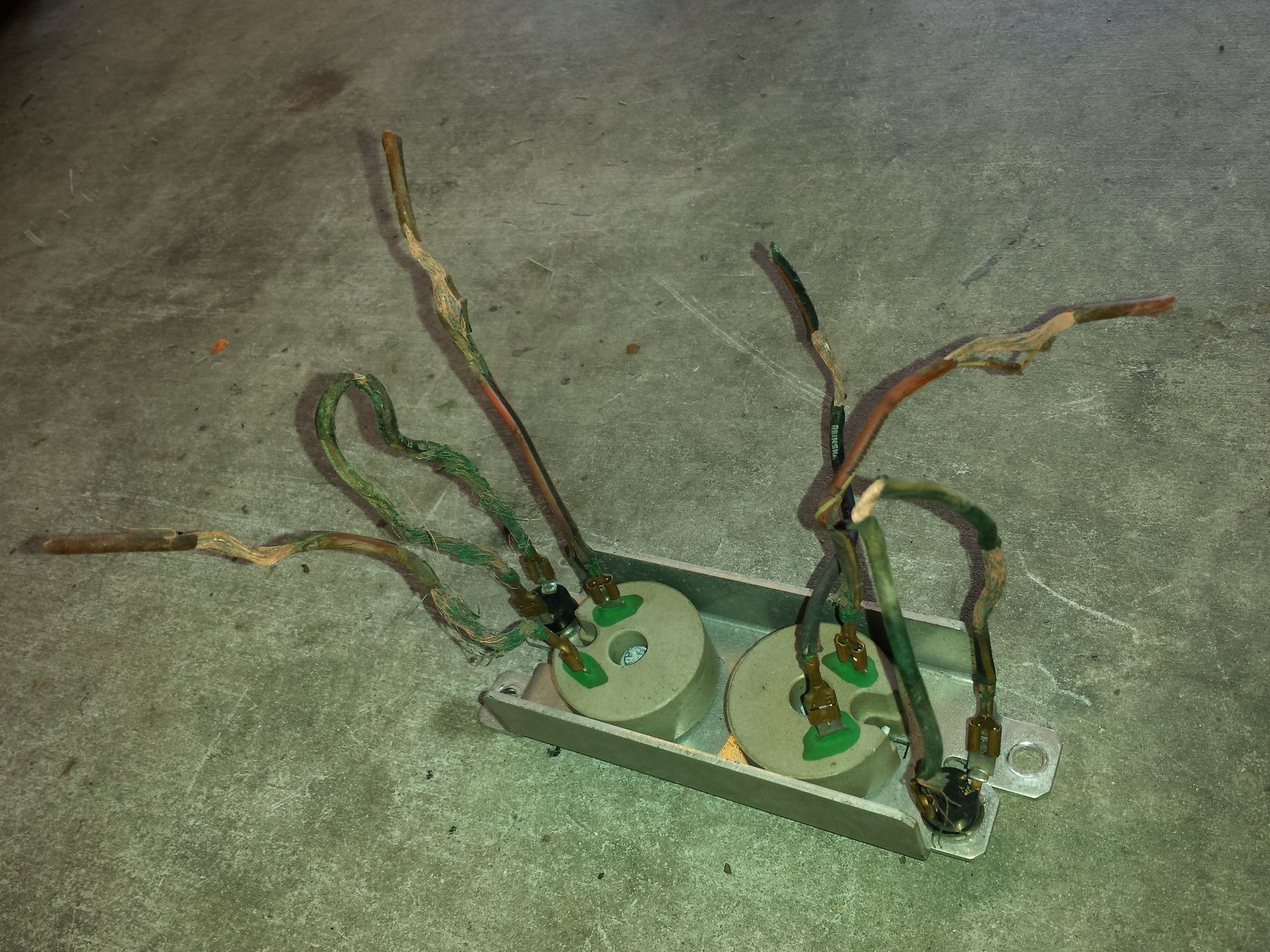
I diagnosed today why my driver side fan wont run in low speed, but runs in high speed. The 8 wire harness behind the glove compartment was completely corroded and practically crumbled in my hand for about 12" from the resistors. The problem is, that area is really hard to word with in the first place, and so much of the wiring crumbled that I don't think there will be an easy way to splice fresh wire back into it.
Problem number 2 is that I managed to damage the resistor pack in trying to pull off the seized terminals. I've seen some resistor packs that just have the 2 wires each to each resistor, and some that also have 4 additional wires, 2 on little plugs on the side of the resistors.
The one on my 86 NA has the additional wiring; what are those extra 4 wires for? Also, how can I temporarily bypass the resistors to keep my fans working in high until I can replace the wiring and resistors?
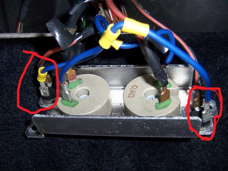
Nobody knows the reason why there are two styles of resistor packs? I'm trying to figure out the purpose of the extra 4 wires shown circled in red, and why some cars have them and some don't. My reason is that the plugs broke off the silver metal tray and crumbled to pieces, and I'm trying to see if I need a new resistor pack or if my fans will work properly with just the 4 wires on the resistors them selves. The picture below is one I grabbed from the web, my wiring was a mess and was the ultimate source of my issue.
I believe those extra four wires are for a thermal cutoff switch. So if the resistors/mounting plate gets too hot, the thermal switch will cut the power until they cool down.
I could be wrong but that is what they look to plug into.
I think pdxfj is right. Yours and the one in your pic are both inside the cabin right? The other type goes outside, in the rear corner of the battery tray. Maybe that's why the temp switch isn't needed on the later ones. From the wiring diagrams, it looks to be an 86 vs later thing. The early diagram shows each fan wire going through something marked "TS" before the fan resistor (maybe thermo switch?). Late diagram shows only the resistors.
can anyone confirm that? That's the first time ive ever heard of such a thing in all the years ive been working on these cars.
edit: yeah mine is in the cabin, its an 86. the resistor pack on my 87 isnunder the hood and does not have the extra 4 wires. is it safe to bypass the two thermal switches on an 86? the switches broke off the silver tray so my choices are run without the thermal protectiom of buy a used 86 resistor pack for ~75-100 dollars.
Also does anyone know how much power these things dissipate? I've read 70 watts combined which seems plausible for a pair of 1.5 ohm resistors in circuits that each draw ~15 amps or so. I'm wondering if I could build my own resistor pack.
Also does anyone know how much power these things dissipate? I've read 70 watts combined which seems plausible for a pair of 1.5 ohm resistors in circuits that each draw ~15 amps or so. I'm wondering if I could build my own resistor pack.
I think they're 0.9 ohms based on both the wiring diagrams and your pics. At 15 amps that would mean 13.5 volts, which sounds about right for the alternator voltage. But I think that would be over 200 watts wouldn't it? I am not sure about that but I think that's right.
I wouldn't bypass those switches unless you are going to relocate the whole thing to the engine bay...I'm guessing they're there for a reason. Maybe you could replace the individual resistor that's damaged though: http://www.ebay.com/itm/Porsche-944-...dU~nIv&vxp=mtr
EDIT sorry I see now it was the switches that broke not the resistors.
Yeah, 15 amps into .9 ohms @ 13.5 volts is over 200 watts per resistor, but in reality my alternator is only putting out 12.9 volts thereabouts and the resistors measure 1.5 ohms each + the resistance of the wiring. An impedance of 1.8 ohms driven by 12.9 volts implies a current through the resistor of only a little over 7 amps, and a dissipation of about 93 watts per resistor. That's still quite a lot of heat.
Edit: FWIW I found some new wirewound chassis mount resistors, 1 ohm resistance rated for 230w. 35/ea but I have to buy 10.
Yeah, 15 amps into .9 ohms @ 13.5 volts is over 200 watts per resistor, but in reality my alternator is only putting out 12.9 volts thereabouts and the resistors measure 1.5 ohms each + the resistance of the wiring. An impedance of 1.8 ohms driven by 12.9 volts implies a current through the resistor of only a little over 7 amps, and a dissipation of about 93 watts per resistor. That's still quite a lot of heat.
I see what you mean. Actually, I had another thought - using the full voltage for this calculation implies that all the energy is being turned into heat by the resistor doesn't it? So maybe it is much less heat dissipation than we thought. Should we be using the voltage drop across the resistor instead?
I see what you mean. Actually, I had another thought - using the full voltage for this calculation implies that all the energy is being turned into heat by the resistor doesn't it? So maybe it is much less heat dissipation than we thought. Should we be using the voltage drop across the resistor instead?
Perhaps; in a series DC circuit, the sum of all the voltage drops is equal to the source voltage. So, to answer this we would need to know the resistance of the fan motor to know how much voltage both the motor and the resistor were respectively dropping. I dont have a spare fan handy to measure, but lets assume its something reasonable like 10 ohms. Then you have ~1.2 volt drop across the resistor and ~11.7 volt drop across the fan motor.
1.2 volts into a 1.5 ohm load allows only .8 amps to flow and dissipates less than a watt of power. That surely isn't right either.
The voltage drop over the resistor is the voltage you should use. You need to measure the circuit with a working resistor to calculate how much power dissipation there is. Motors are dynamic loads so you can't just measure the impedance of the fan to calculate the current. The easiest and most accurate way to calculate the power dissipation would be to measure the current and voltage drop on the resistor when the fan is running. Only very expensive ohm meters are good at measuring such low resistances, so I wouldn't count on that measurement.
buuuut, if the fan is something more like .75 ohms, than that means the drop across the resistor is actually more like 7ish volts, and 7 volts into 1.5 ohms lets 4.7 amps flow and dissipates ~32 watts, which is close to the 70 watts combined figure I've heard.
Edit: Thanks konakat, I was hoping you or another resident electrical guru would chime in. Any idea for the approximate dissipation of each resistor?
But isn't current is the same everywhere in series? So if the fan was 0.75 and the resistor 1.5, that would give you 5.7 amps. I think that is the current you would need to use, along with the voltage drop of just the resistor, to calculate the power dissipated by that resistor right? Not that it matters in practice, since you have to measure the current anyway as Konkat says.
But the fans draw ~15 amps each in steady state and ~25 each on startup, so that would mean current through the resistor would be 15 amps, but at 1.5 ohms resistance that would mean the input voltage would be higher than my alternator is putting out.
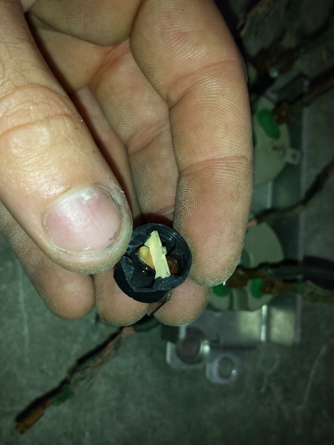
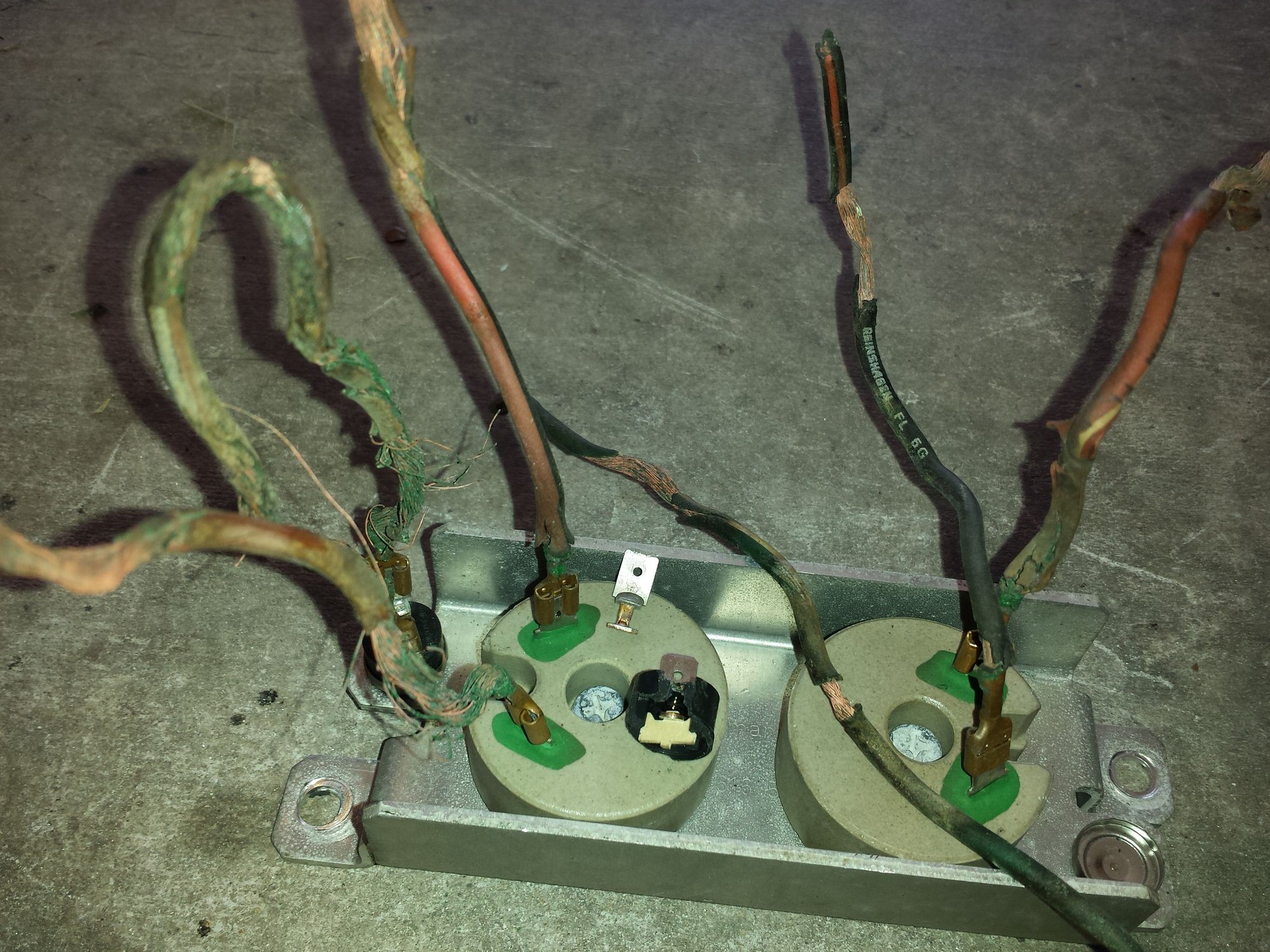
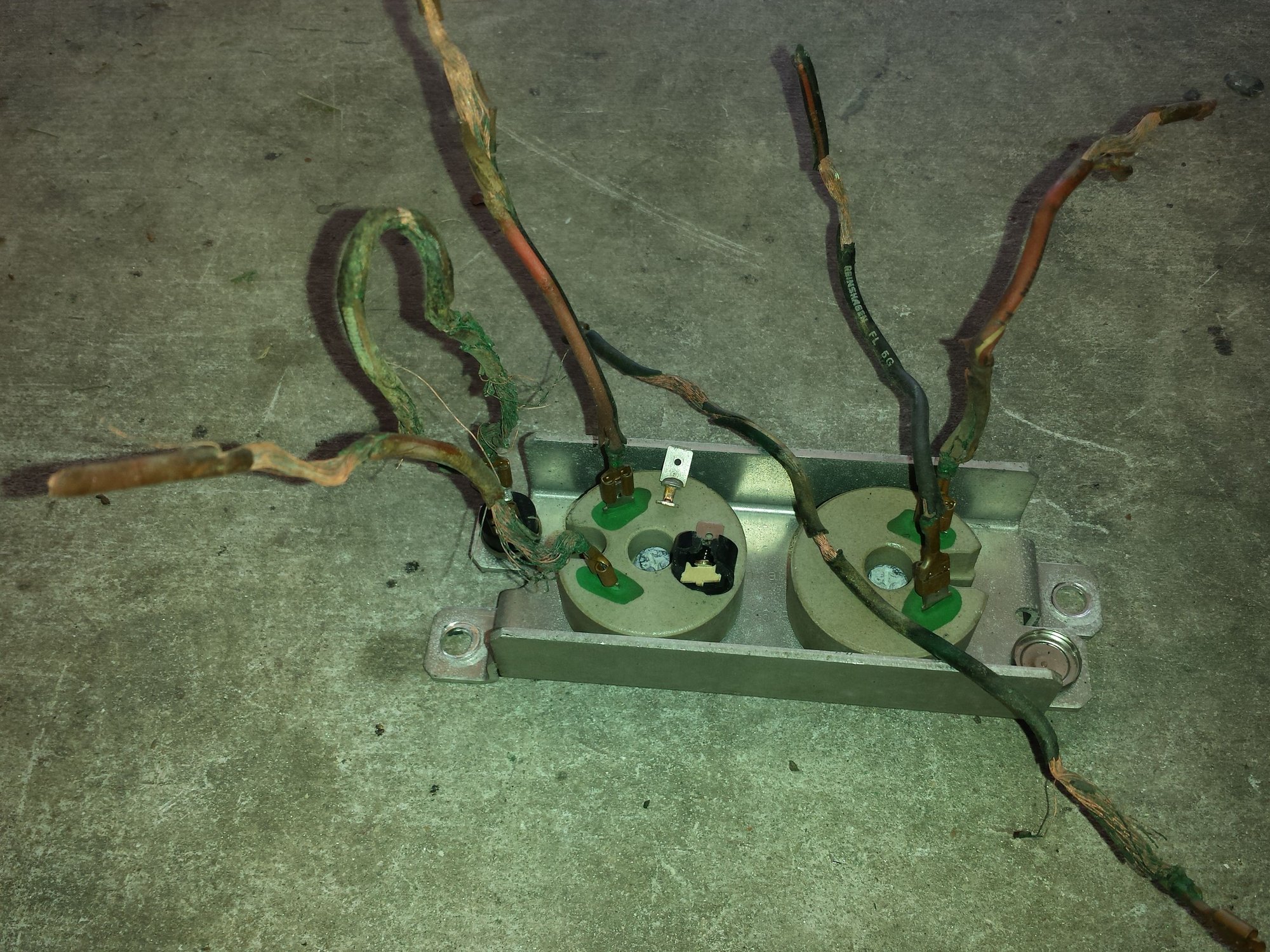
Also for posterity, here are some pics of my actual wiring, as well as the switches. They marked "microTherm" on the back, implying they are some kind of thermal protection but I fail to see how they work. Inside, they have a small spring which forces the two contacts against each other. Thing is, as you can see from the images showing how they were wired, the two contacts are simply bridged with a jumper and are not actually wired into the circuit with the resistors, so I don't see how they'd interupt the circuit in cases of high temps; really I don't see their point at all.
The
normally closed contacts open when reaching the pre-
defined temperature by snapping of a bimetal disc.
Temperature setting is defined through conditioning
(aging, stamping, ...) of the disc. After a corresponding
cooling down, the bimetal disc snaps back to the original
position and closes the current circuit again
 08-08-2016, 03:00 AM