When you click on links to various merchants on this site and make a purchase, this can result in this site earning a commission. Affiliate programs and affiliations include, but are not limited to, the eBay Partner Network.
Have my AIM mxl2 hooked up to the ecu and see the Fuel tank level channel but there is no value. It's a 2009 cayman. Do I need to hookup an iron canyon fuel sensor? If so, anyone know the min /max ohms for the fuel level sensor?
Can't say for the Cayman but I used the iron canyon sensor for my miata and I drained the tank, put a gallon in at a time and recorded the reading, then made a custom sensor I think and mapped the readings to gallons.
Can't say for the Cayman but I used the iron canyon sensor for my miata and I drained the tank, put a gallon in at a time and recorded the reading, then made a custom sensor I think and mapped the readings to gallons.
Yep... That's my last resort. Just want to make sure I'm not missing anything obvious.
I also have a 2009 Cayman S and an MXL Pista (older than your model) and it picks up fuel level fine.
Not sure how I can help but glad to look at my setup and compare with yours.
I also have a 2009 Cayman S and an MXL Pista (older than your model) and it picks up fuel level fine.
Not sure how I can help but glad to look at my setup and compare with yours.
Thank you!
I believe I have solved the issue.
With my seating position and steering wheel diameter, the wheel was blocking my shift lights. So I removed the instrument cluster and set the MXL2 further back.
Evidently, the DME doesn't like not having the instrument cluster. Once I plug in the instrument cluster, the Fuel Level feed works.
I'm going to hook up the PIWIS to the car and disable the Instrument Cluster and see if that keeps the DME from erroring out.
I see other cars without the instrument cluster and assume they've just disabled it.
I should have that done this weekend. I'll post the results, but I believe that is the case.
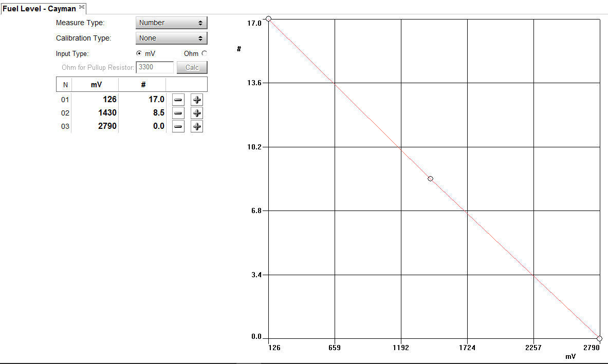
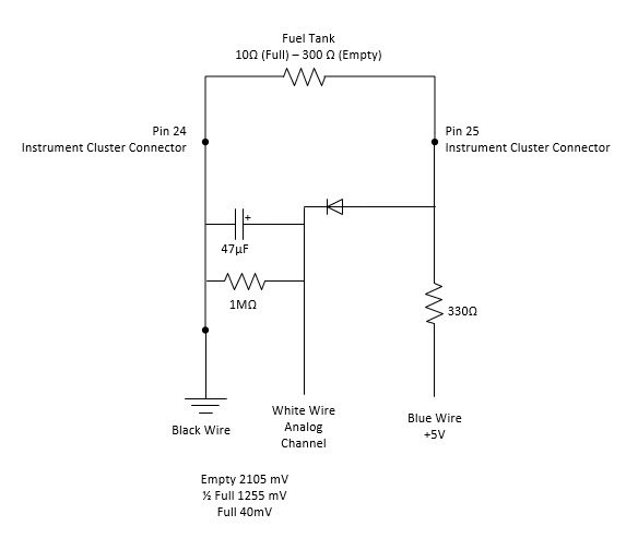
Got it setup... So full is 10 ohms, empty is 300 ohms. Didn't have a 300 ohm resistor, so used a 1k resistor and set it up as an Up resistor.
From Channel 2 Binder 719, connected GND to one wire (pin 24 on the instrument cluster connector) and to the other connector (pin 25 on the instrument cluster connector) and the channel 2 white (+ signal) together. Took those two wires and connected to one side of the resistor. To the other side of the resistor, I connected the +5v from Channel 2. This puts around 500mA through the circuit. The voltage at the MXL2 was 126mV up to 2790mV. This will change depending on the size resistor. Ideally, I would have used a 300 ohm. Now I need to dampen the signal.
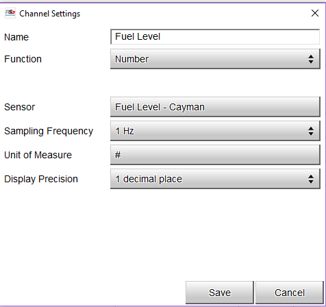
Create a new Custom Sensor:
I had my tank sensor connector to Channel 2, so I enabled that in my MXL2 configuration and linked it to my new sensor:
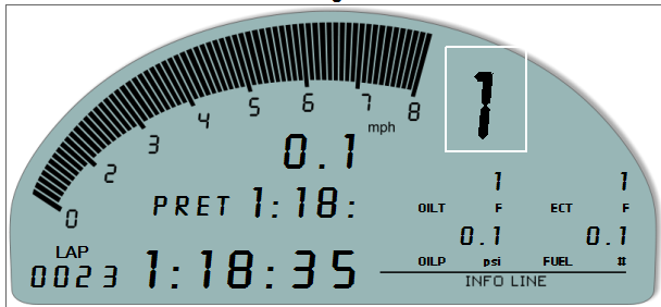
I then added it to my Display:
I then set an alarm at 4 gallons to give me a warning. Once I size the capacitor to put across the ground to the signal, it should dampen the measured voltage. I'll update here once I get the right capacitor sized.
__________________ -Peter Krause www.peterkrause.net www.gofasternow.com
"Combining the Art and Science of Driving Fast!"
Specializing in Professional, Private Driver Performance Evaluation and Optimization
Consultation Available Remotely and at VIRginia International Raceway
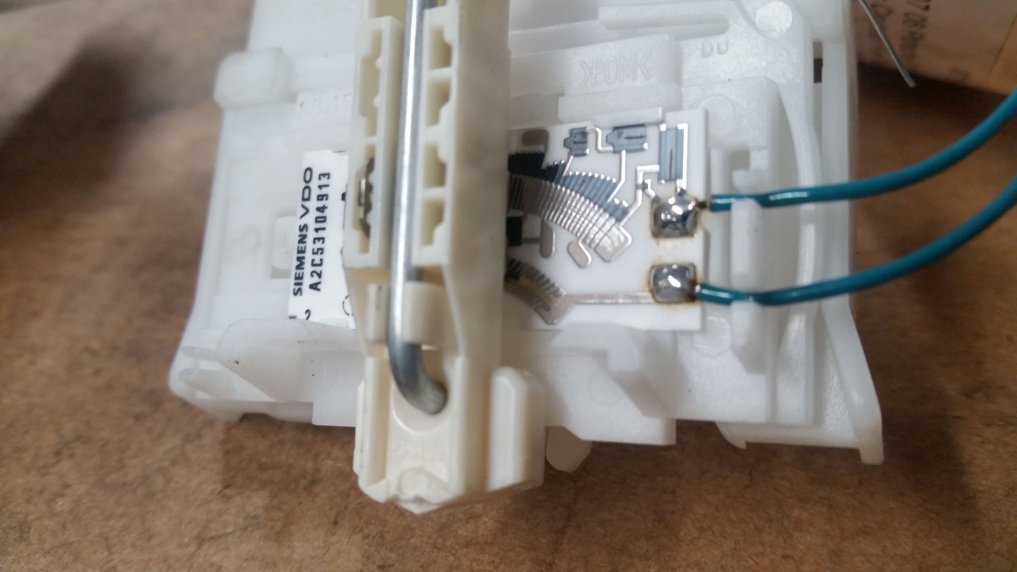
Thick film multi-layer circuit on an Aluminum Oxide substrate. Has trimmed resistors (see laser scribes) that more than likely set it to a linear representation of tank status, even though geometry of the tank is not uniform, top to bottom.
Modified the circuit with a different resistor and added a 47 microFarad capacitor to dampen the movement of the float in the tank... Have a breadboard coming in and going to build a small 'box' to package. I'll confirm the numbers once I have it all built out tomorrow...
Now if we can only figure out oil level from the pulse signal on pin 11.

 06-16-2016, 02:04 PM