When you click on links to various merchants on this site and make a purchase, this can result in this site earning a commission. Affiliate programs and affiliations include, but are not limited to, the eBay Partner Network.
2012 CTT Clockspring and Steering Angle Sensor rebuild/teardown w/pics
For the past month I've been dealing with an intermittent PSM Failure. This issue affected multiple systems disabling ACC/PAS and auto start/stop. Upon scanning the car, the PSM module threw two codes:
- 030A0E: Steering angle sensor (steering wheel electronics), function restriction
- 030A88: No communication with steering wheel electronics control unit (CAN bus, chassis)
Replaced the battery (which needed to be done anyway) and ran a re-calibration of the steering angle sensor. Still the problem persisted at random intervals. During the troubleshooting process, two possibilities came to mind for what was causing this issue. Firstly, as the PSM failure was intermittent and would occasionally kick off, this led me to believe that the issue was harness/wiring related. Secondly, this issue began during a drop in temperature, further bolstering the possibility that this was a wiring issue. Since I knew that this was an intermittent issue between the CAN (chassis) and the clockspring (I had pulled, cleaned, and tested the harnesses to the DME and PSM modules earlier in the week), this narrowed down my search area.
Since there are tons of forum posts on removal of the wheel/clockspring/airbag/etc., I'll skip straight to the good part. Also, sorry I don't have complete pictures of this. I was trying to remember wheel positions and not destroy this thing.
****NOTE: NOT FOR THE FAINT OF HEART. MARK ALL POSITIONS CLEARLY BEFORE DISASSEMBLY OR ELSE THIS THING MAY NOT GO BACK TOGETHER CORRECTLY. YOU'VE BEEN WARNED****
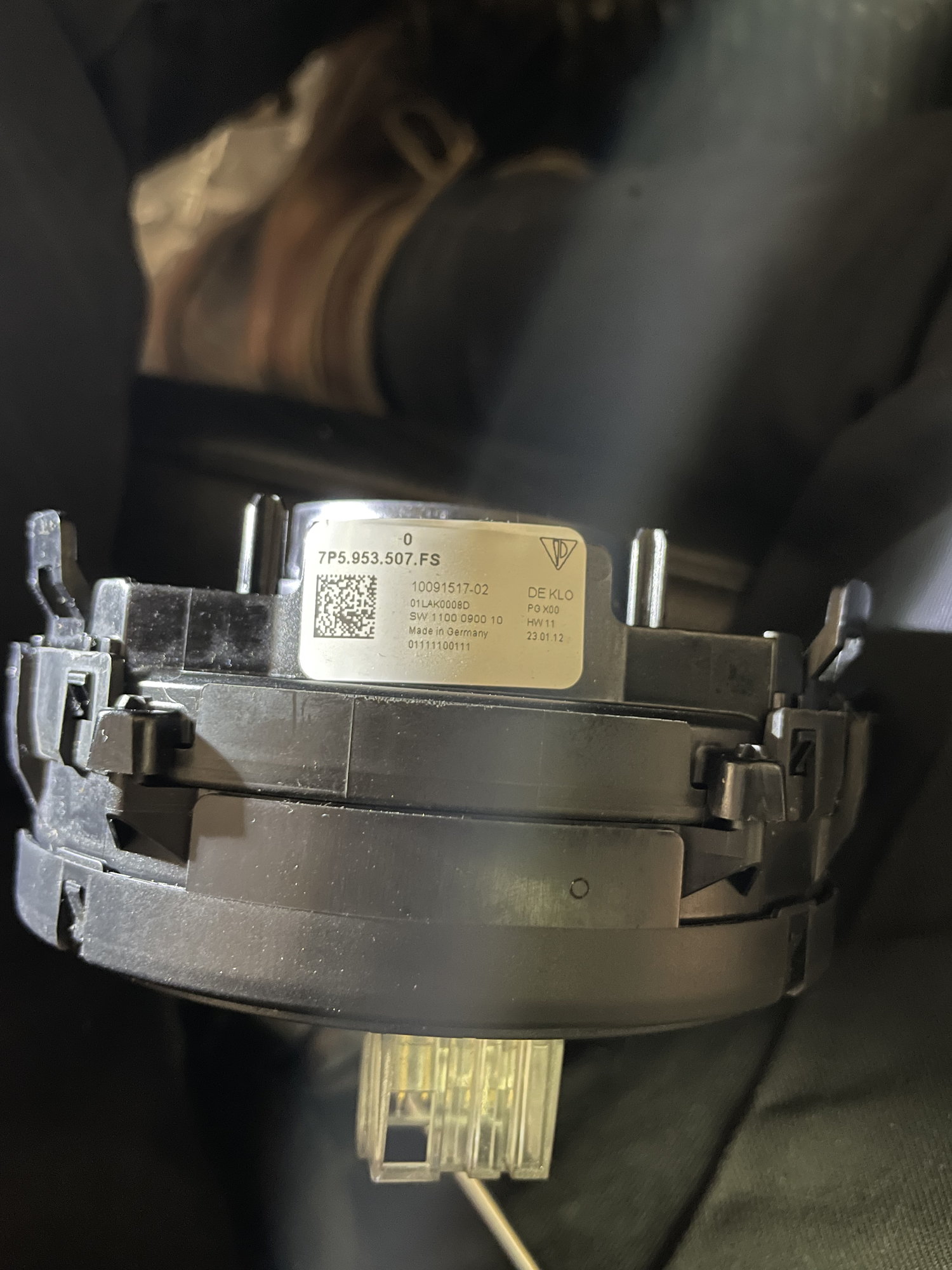
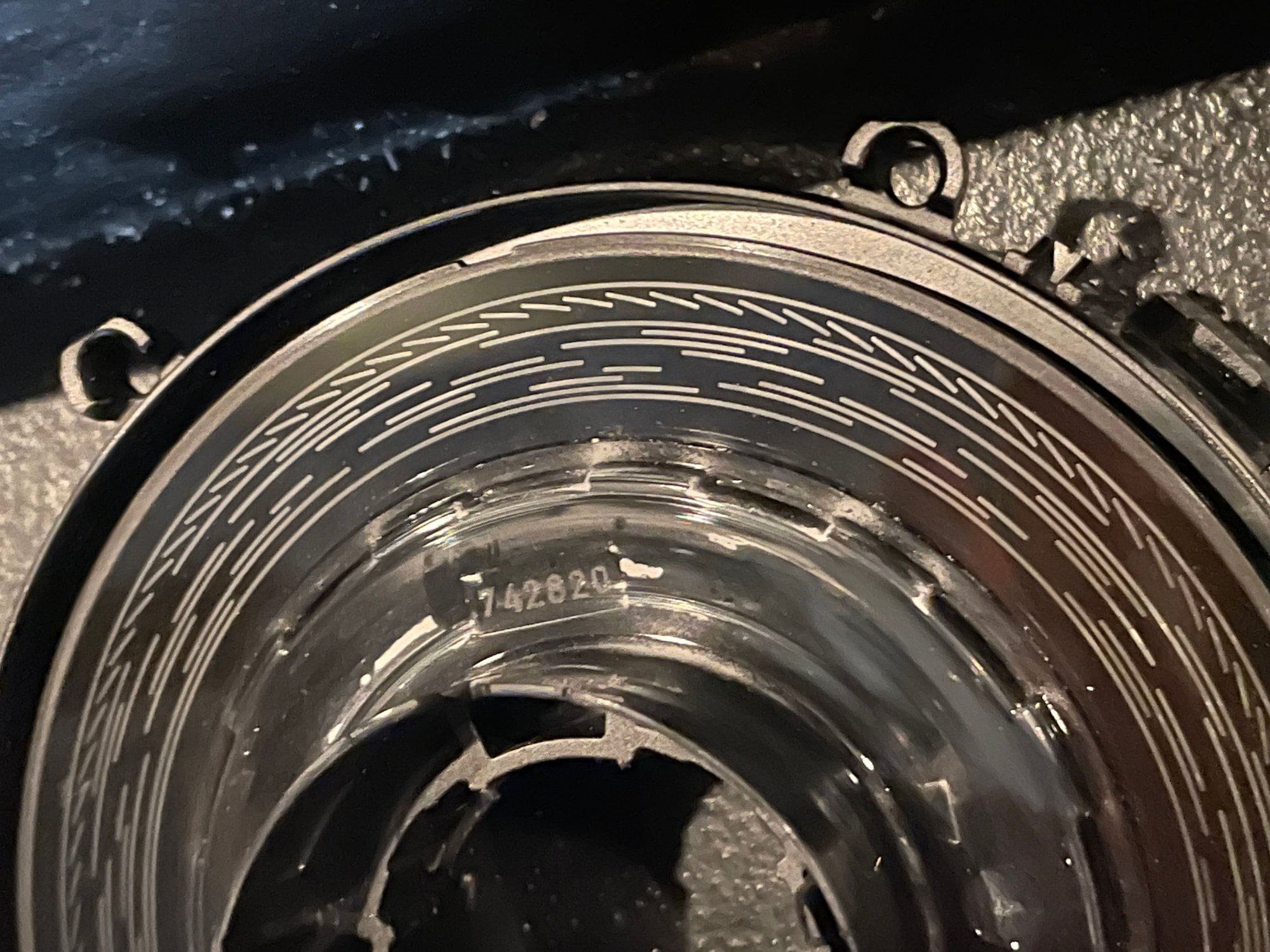
Disconnected my battery negative and pulled the clockspring. Began to disassemble the module by first releasing the tabs (shown in picture below) for the front slip-ring with a small pick. Marked all starting positions with a permanent marker prior to disassembly.
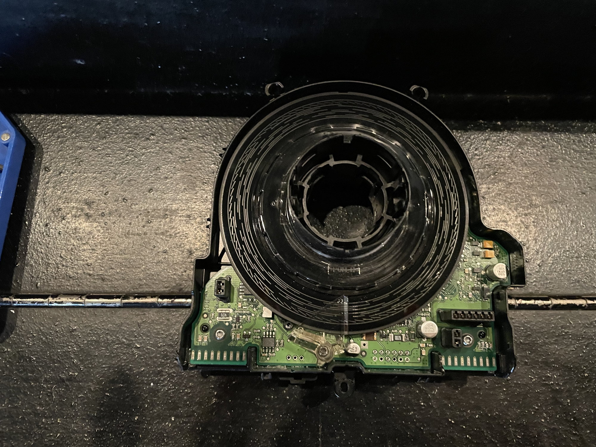
Once the slip ring was removed, you then have access to the front cover of the control module/steering angle sensor assembly. This comes apart from the rear of the case by carefully prying up on the various tabs. You end up with this:
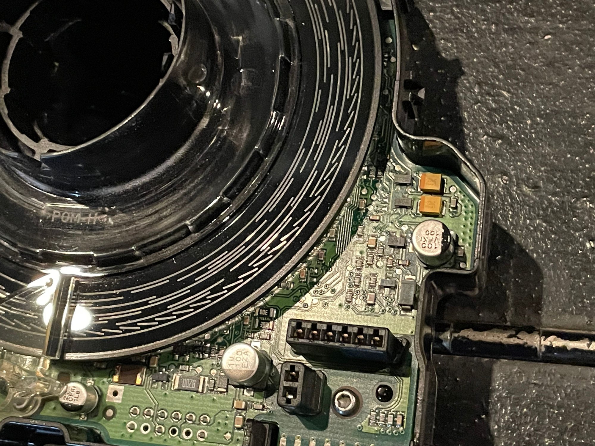
This thing was DIRTY. There was an unidentifiable white powder all over the printed encoder disk and PCB inside of the module which may have been causing some interference between the optical sensor and the encoder disk.
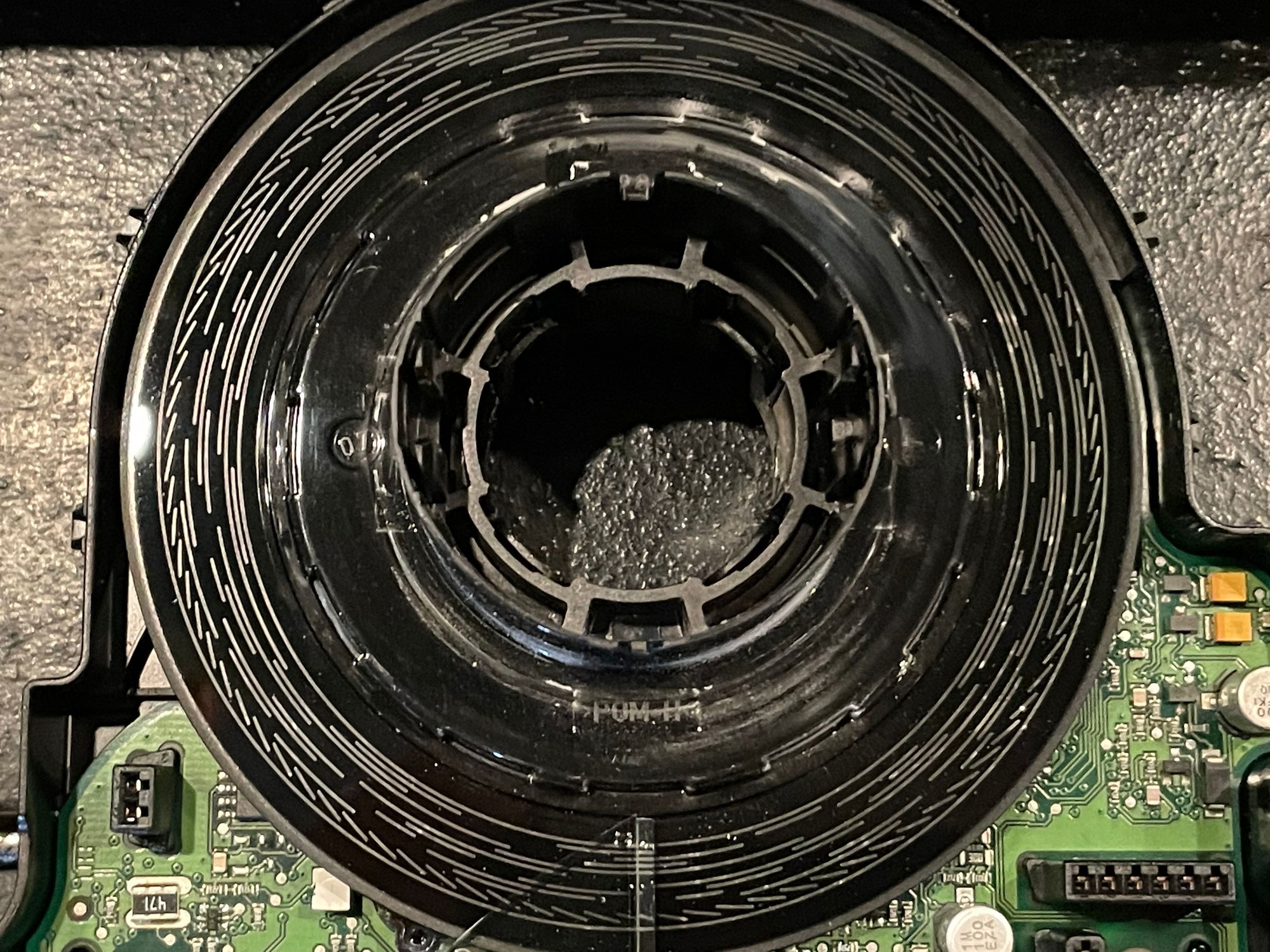
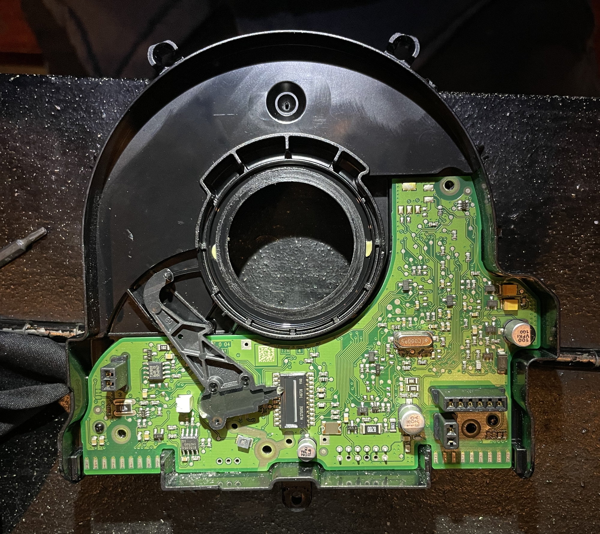
Removed the encoder disk by first removing the clear plastic retainer/reflector @ the 6 o'clock position on the disk. There is a plastic circular retainer at the rear of the disk hub that releases with four tabs. Once the disk has been removed you end up with this:
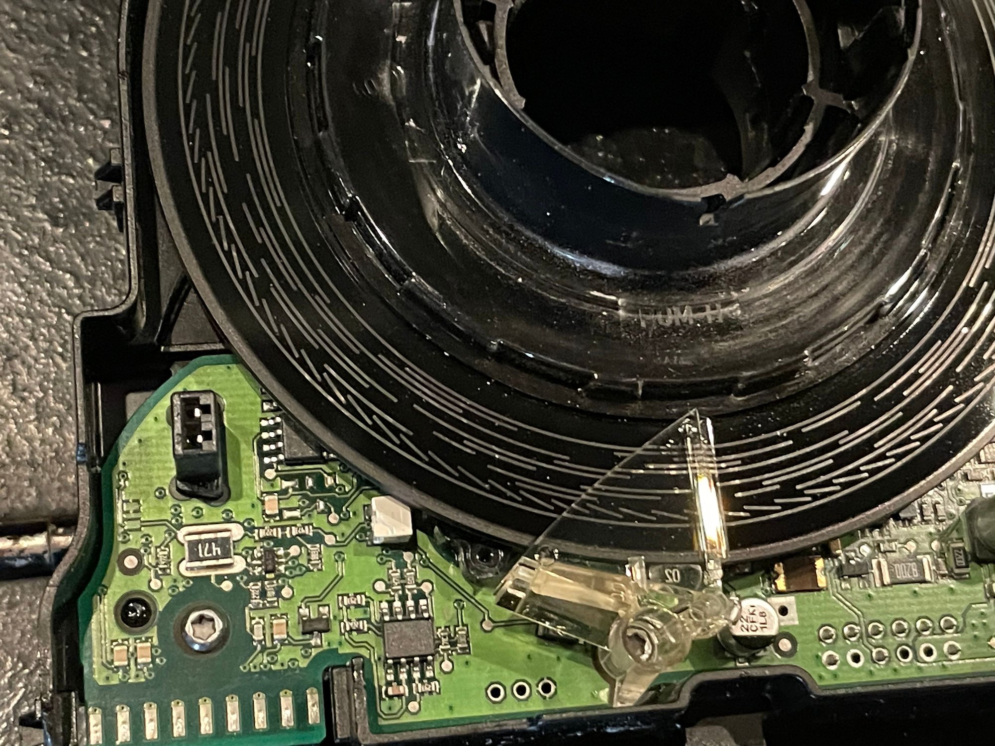
So now I had to remove the sensor wiper (to the left of the Melexis MLX75003E light-to-voltage sensor) which is on a pivot point to a holder on the rear of the unit. Used a small safety torx and a pick to get this carefully pushed out of the front of the circuit board. From there, the remaining three torx screws can be removed from the board and it comes free. Be careful of the bending the pins slotting out from the rear case. You don't want to stress or bend these.
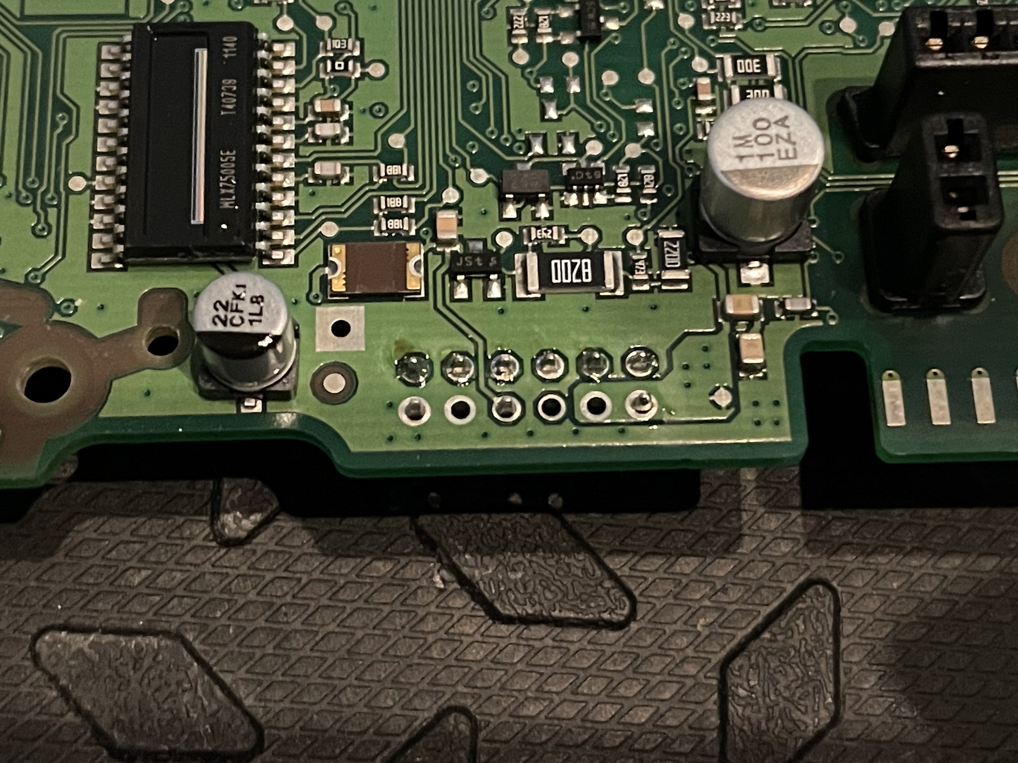
Okay, so here I found something that I didn't like. The set of 12 pins (that you were being so careful not to bend) at the bottom middle of the circuit board contain the signals that go to the CAN bus. We know from the computer data line wiring diagram that pin 5 and pin 6 are our respective CAN chassis low and high signals to the gateway control unit. But look at how these pins are soldered onto the board! They're barely tacked. This could easily cause an intermittent connection especially with expansion and contraction in cold weather. With the PCB pulled, I fired up the iron and gave these pins an appropriate soldering. So you can see the difference, the top row of 6 has been re-soldered and the bottom row has not.
After this I gently cleaned the pins and housings with some alcohol and cotton swabs. Pins were pretty dirty and I just wanted to remove the white mystery powder from the housings. I then turned my attention to the encoder disk. I used rubbing alcohol and a microfiber cloth on the top of the disk. I opted not to use alcohol on the bottom of the disk as I didn't know how it would interact with the encoding signal printed on that side. I then re-assembled the unit. Board went in no problem. Then came the sensor wiper. Since there was no good way of marking its position, after inserting it into its holder slot, I positioned it center to the sensor. The encoder disk has a grooved ledger on the rear that a tab sticking out of the sensor wiper follows. As the disk turns, the wiper's position moves across the sensor. I figured that centering this wiper, coupled with my marks on the disk's hub would be enough to get me centered and calibrated. I seated the disk, then snapped the rear retainer back onto the hub. Examining the sensor wiper with a small light, I was able to turn the encoder disk and verify that the wiper was moving freely along the sensor led by the groove in the rear of the disk. I centered the disk with my marks to the original noon position, and the sensor wiper roughly in the middle of the sensor. Reinstalled the clear plastic retainer/reflector and the rest of the torx screws to the PCB before snapping the top case and front slip ring back onto the front of the module.
Reinstalled the module back onto the steering column with the steering wheel and airbag, reconnected the battery, and performed an SAS calibration with my Foxwell NT530. No codes and so far so good!

 12-26-2022, 07:10 PM