When you click on links to various merchants on this site and make a purchase, this can result in this site earning a commission. Affiliate programs and affiliations include, but are not limited to, the eBay Partner Network.
I am wiring indicators, horn and brights (for flash) to an OMP steering wheel's buttons. I need the wire diagram to the indicator switch on the steering column so I know which wires to tap (horn is done already).
Does anyone have this diagram or know where I can find it?
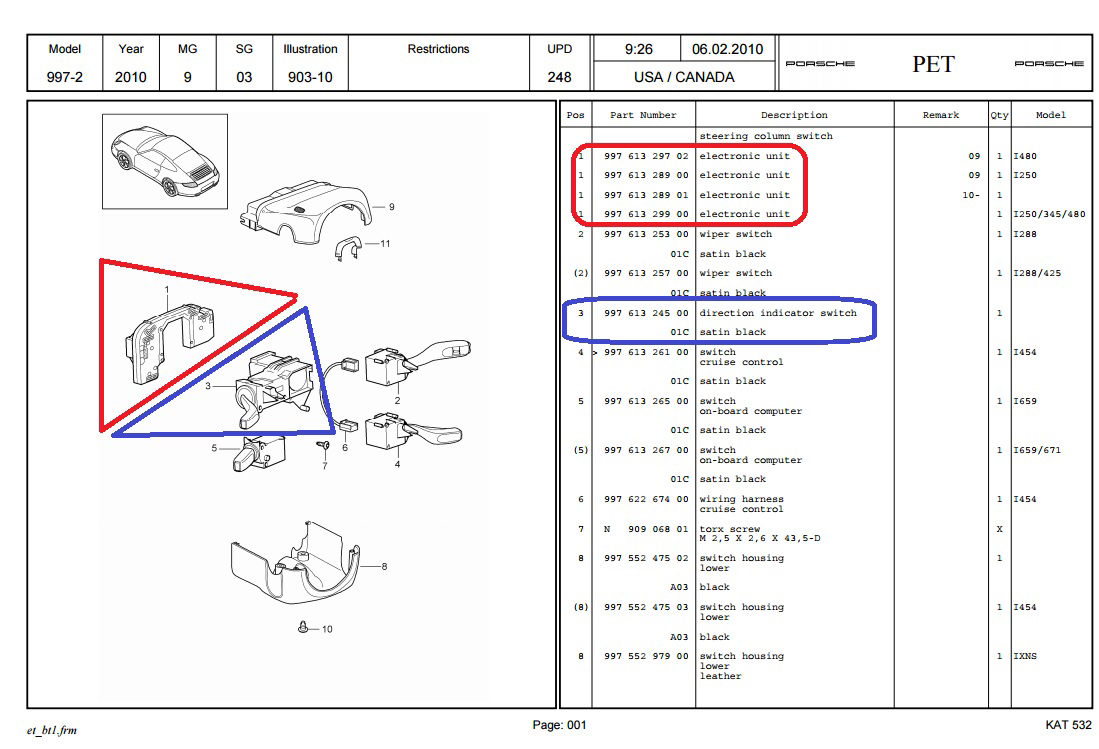
Edit: Looks like i need the wire diagram for these two specific parts,1 and 3 in the embedded image. 3 is the indicator switch while 1 is the control unit and would be helpful to have but redundant if I have 3.
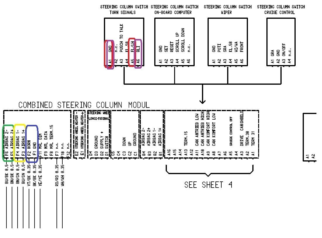
Here is the diagram in question. I've highlighted the terminals for the following: 1) Low speed steering wheel airbag for jumping with a 2.8ohm .5W resistor 2) High speed steering wheel airbag for jumping with a 2.8ohm .5W resistor 3) Horn for wiring to steering wheel 4) High beam flash for wiring to steering wheel 5) Direction Indicators for wiring to steering wheel
I'm still figuring out the relay that differentiates left from light indicator and will post that once I have it.


 08-28-2015, 12:50 PM