When you click on links to various merchants on this site and make a purchase, this can result in this site earning a commission. Affiliate programs and affiliations include, but are not limited to, the eBay Partner Network.
I have just finished replacing my ballast resistor on the passenger side and I've done it a lot cheaper than using the genuine Porsche Ballast resistor. I'll do a step by step guide but if anyone wants any help, message me.
I'll describe the passenger side but obviously if yours is drivers side then alter as required.
Before you start, go to RS or similar and get a 0.5R 100W (RS code 188-071) resistor. This will cost you about �5 inc VAT.
1. Remove the wheel and support on a suitable axle stand.
2. Remove the wheel arch liner which will give you access to the ballast resistor wiring.
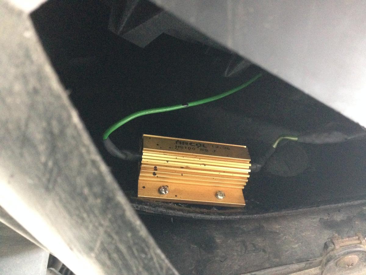
3. You should see the resistor on its clamp with the wiring coming from it.
4. I would disconnect the battery for safety at this point.
5. Cut the wiring as close to the old ballast resistor as possible.
6. Remove the old resistor and bin it.
7. Identify the three wires (green, white and green/white).
Green = Low speed fan supply
White = High speed fan supply
Green/White = Output to fan motor
8. I suggest you get hold of a good soldering iron, you will need something quite powerful or use good quality crimp connectors and cover all joints with heatshrink, the stuff with adhesive in is the best choice.
9. Solder the White and Green/White wires to one side of the resistor and then cover with heatshrink.
10. Solder the Green wire to the OTHER end of the resistor and cover the joint with heatshrink.
11. Drill a couple of holes so you mount the new resistor where the old one used to be. Make sure its in the airflow of the fan.
To test the new resistor.
Reconnect the battery and make sure all fuses are good.
First of all you need to know where the relays are. Look under the dash above the fusebox and you'll see a row of grey relays (each is marked with a large 53).
Working front to back, they are :
1. Not important for this
2. Passenger side low speed
3. Passenger side high speed
4. Drivers side low speed
5. Drivers side high speed
OK, choose which relay you need to pull, I would suggest high speed first of all.
Once you've pulled the relay, make a short piece of wire ( 100mm) and crimp a blade type connector one each end. Use this to "jump" the relay.
Connect from the top connection (vertical slot) to the bottom horizontal slot. The fan should run at full speed (you'll hear it).
OK, now remove the link and replace the relay.
Do the same again for the low speed and you should hear the fan run at a lower speed.
Remove the link wire and replace all relays.
Replace the wheel liner and roadwheel.
Start the car and put the a/c on and set it to the lowest temperature, give it a few seconds and you should hear both front fans running at low speed.
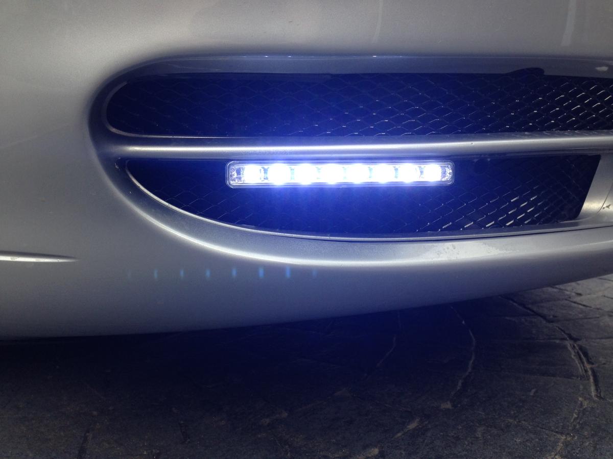
Hopefully the two pictures will work. One shows the new resistor in place and the other shows the front now I've fitted some mesh and DRL's.
If anyone has any questions or needs a hand, message me.
I realize this is an old thread but I hope someone can help me.
I recently replaced the driver's side ballast resistor in my 2001 996 cabriolet. I noticed that both driver and passenger side triangular shaped removable covers are missing from the underside of my car - this probably explains why one resistor went bad due to cold rain.
I haven't been able to find a part number for the cover. Can anyone guide me to a resource with part numbers for under body parts?
one the reason they might fail seems to be that they get super cooled with water splashing on them causing internal fracturing and thus failing
Yes nothing special about them other than the shape/size/availability
you could solder about anything in its place to reduce the voltage as long as it can be mounted safely, not come in contact with any surrounding parts and handle the power requirements
My son just went through this on a computer monitor he bought that had a blown capacitor - the part was sourced out of Canada for $2 and not easy to find, but at the end of the day it fit the needs and solved the problem.
Sorry to bring up this old topic, but I have a question about the missing cover (if there ever was one). I recently had to replace one of my ballast resistors and would like to avoid having to do it again - especially if it's because it got super cooled from splashing rain. Is there supposed to be a louvered cover to protect the ballast resistor, or is it supposed to stay open to allow hot radiator air to flow through? If it is supposed to be covered, could anyone tell me the part number or take a photo to show me how it's supposed to look?
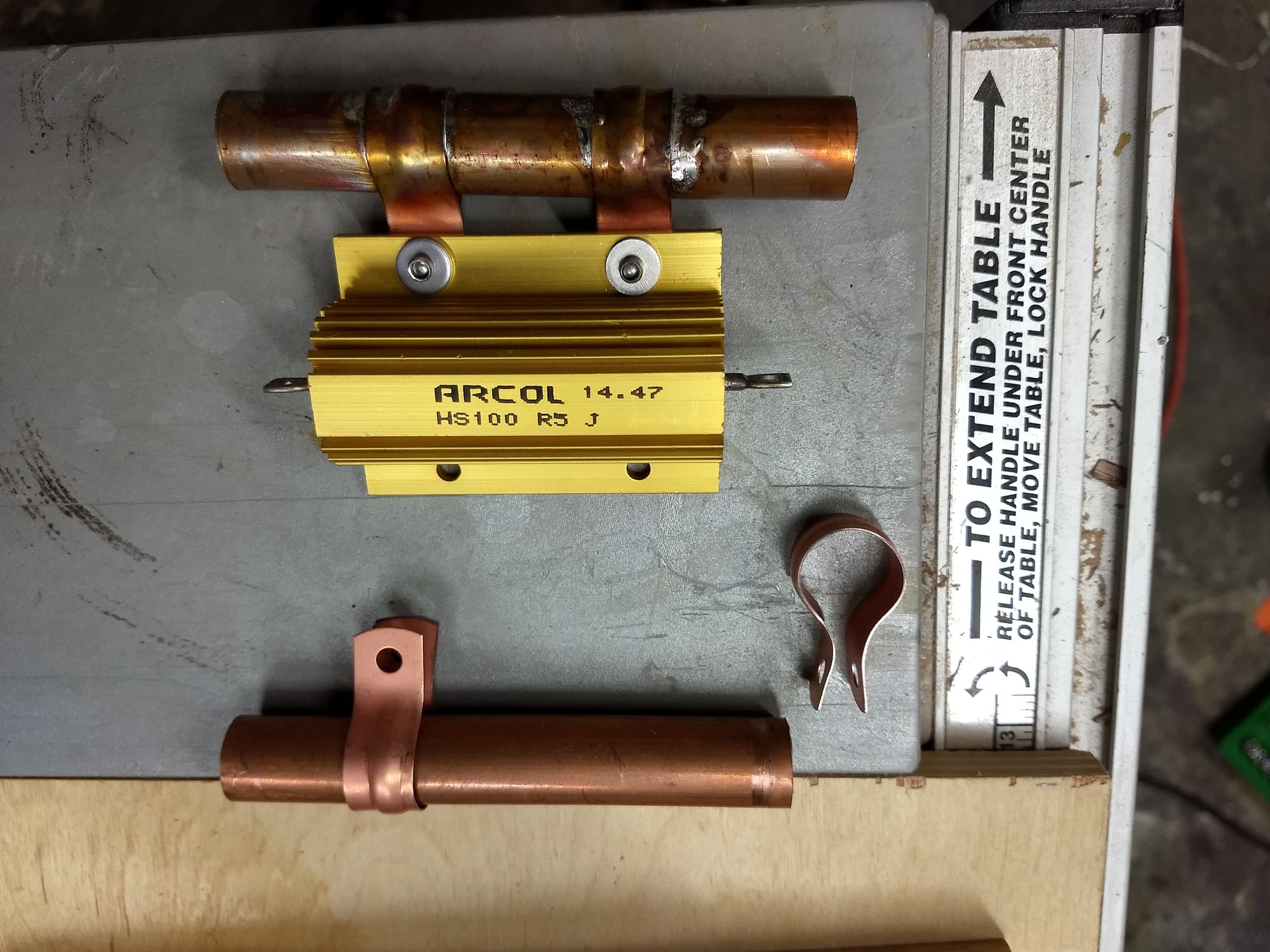
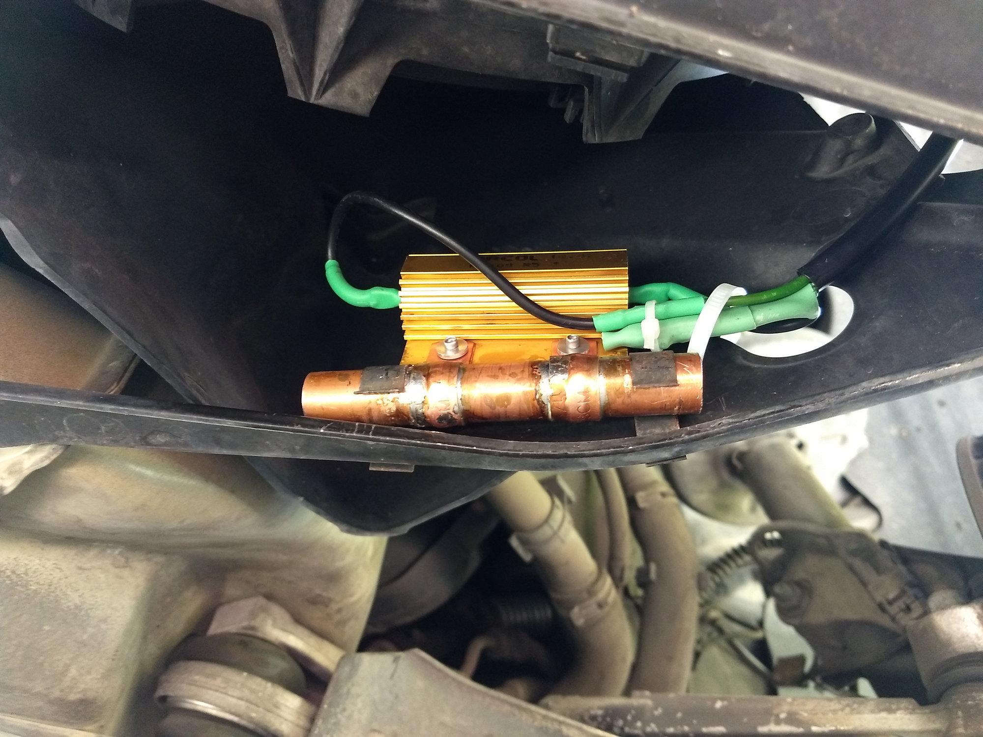
Nothing to add to the electrical info already in this thread but I did try a different mechanical solution to mounting the non OE resistors. The OEM resistors have exactly the same OD as 1/2" copper pipe which gave me an idea...a few pop rivets and some bent 3/4" pipe brackets later....
Thank you for the post. I'd seen others perform this, but they wired it wrong. Since the white and solid green wires come from the same cable loom and go to the factory resistor, they assume they should be soldered together on one end of the replacement resistor. This mis-wiring would result in both high and low speed operations going through the resistor and only getting low speed fan. Thank you for showing the right way
I bought two of these resistors on Amazon for under $8 total (free prime shipping). If you can solder, this is a very cheap, easy repair that maintains the stock functionality. I have a new fan assembly with a new resistor that I will put in eventually, but this was too cheap not to try it out.
I bought two of these resistors on Amazon for under $8 total (free prime shipping). If you can solder, this is a very cheap, easy repair that maintains the stock functionality. I have a new fan assembly with a new resistor that I will put in eventually, but this was too cheap not to try it out.
I have diagnosed a resistor failure on my left fan, what I found on Amazon was this:
I have diagnosed a resistor failure on my left fan, what I found on Amazon was this: https://www.amazon.com/dp/B07FRR63V7...v_ov_lig_dp_it
Is this the one you used or at least is it equivalent? I am not at ease with electronic component equivalences...
Thanks.
Yes, 100 watt 0.5 ohm. That's what I used. Different brand, different color anodizing, same specs.
 05-04-2014, 02:33 PM