When you click on links to various merchants on this site and make a purchase, this can result in this site earning a commission. Affiliate programs and affiliations include, but are not limited to, the eBay Partner Network.
DIY - Testing and Cleaning the Idle Stabilization Valve (ISV)
DIY - Testing and Cleaning the Idle Stabilization Valve (ISV)
This DIY is going to show how to test the ISV using a scope and the steps to
clean the ISV.
Cleaning the ISV
Before testing the ISV, the valve should be cleaned. This valve requires periodic
cleaning to remove carbon deposits that will affect the smooth operation of the
valve.
To remove the valve is very simple following 5 easy steps.
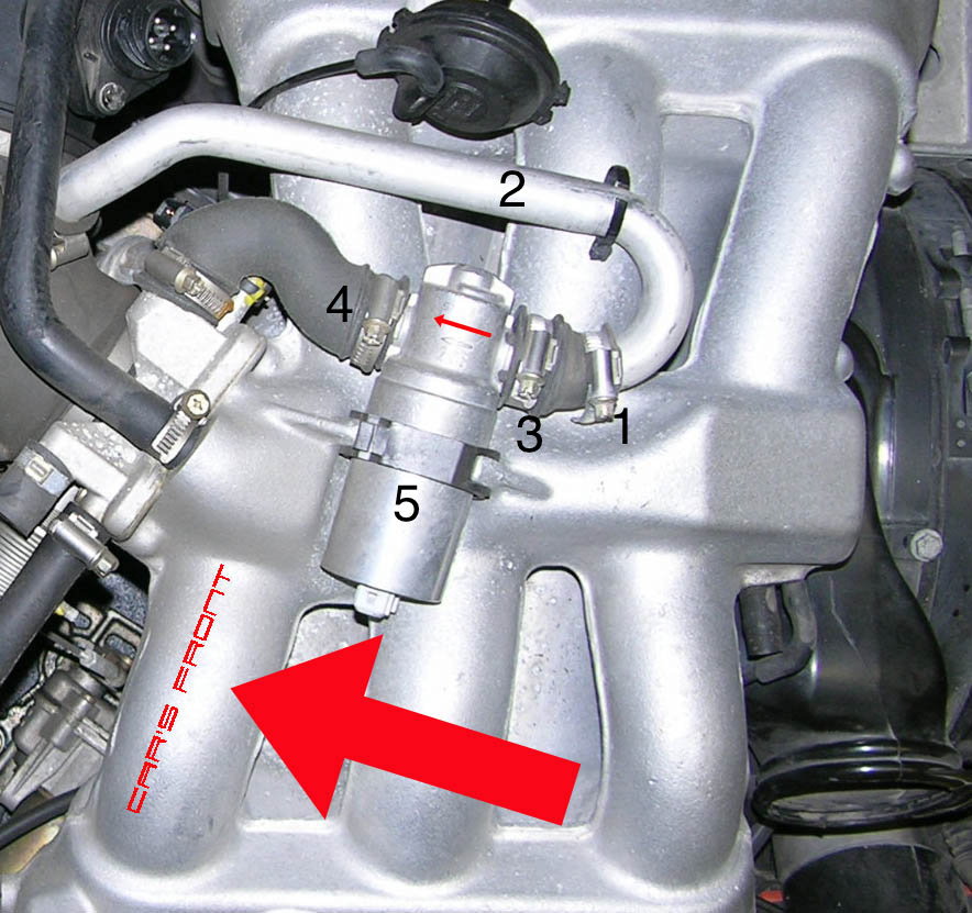
Refer to the following photo, which I found on pcarworkshop.com, where I have
annotated the steps that should be done in order.
By the way, the orientation of the hose clamps in the photo above is wrong. They
may have come from the factory that way but they should be reoriented for easy
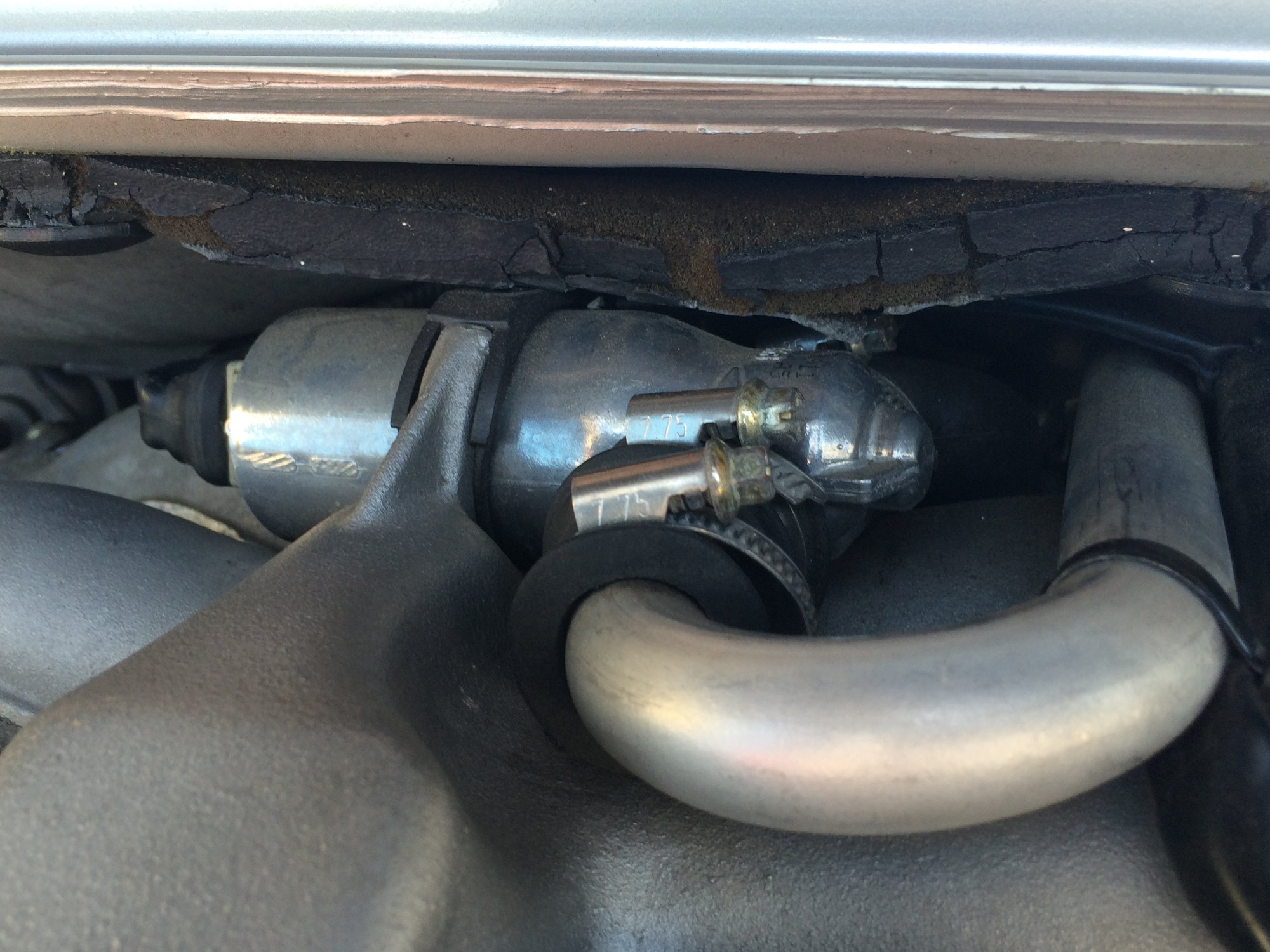
removal. The screws should all point to the right as shown here.
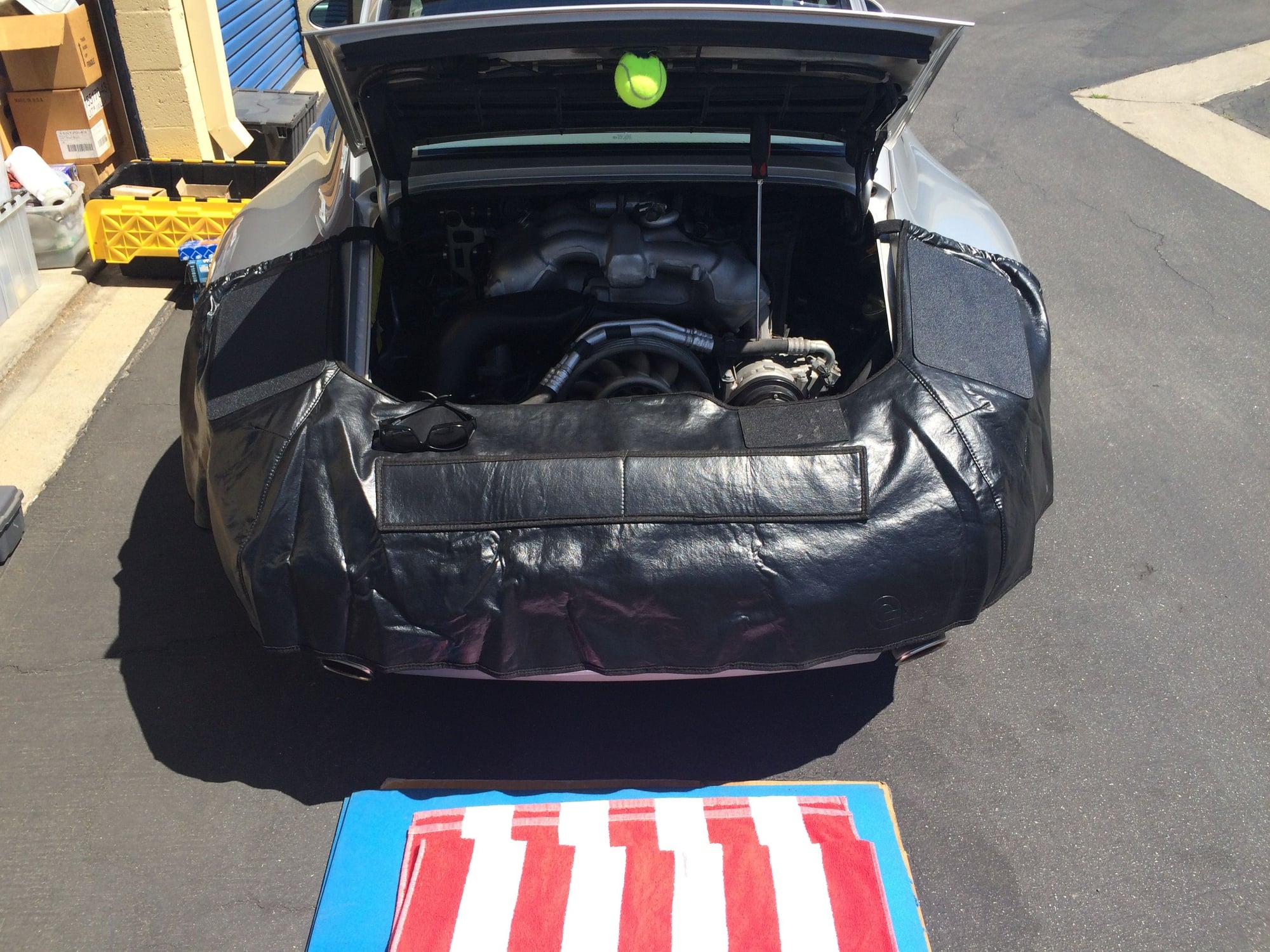
I suggest you protect the rear of the car, use head protection on the latch, and
use a knee pad as shown here.
Remove the wiring harness connector on the left of the valve to get started.
Step 1 - loosen the hose clamp identified as (1).
Step 2 - pull out the pipe and hook it over the vacuum actuator on the right so
it is out of the way.
Step 3 - loosen the hose clamp identified as (3) and pull off the rubber coupling.
Step 4 - loosen the hose clamp identified as (4) and push off the hose with a
large blade screwdriver.
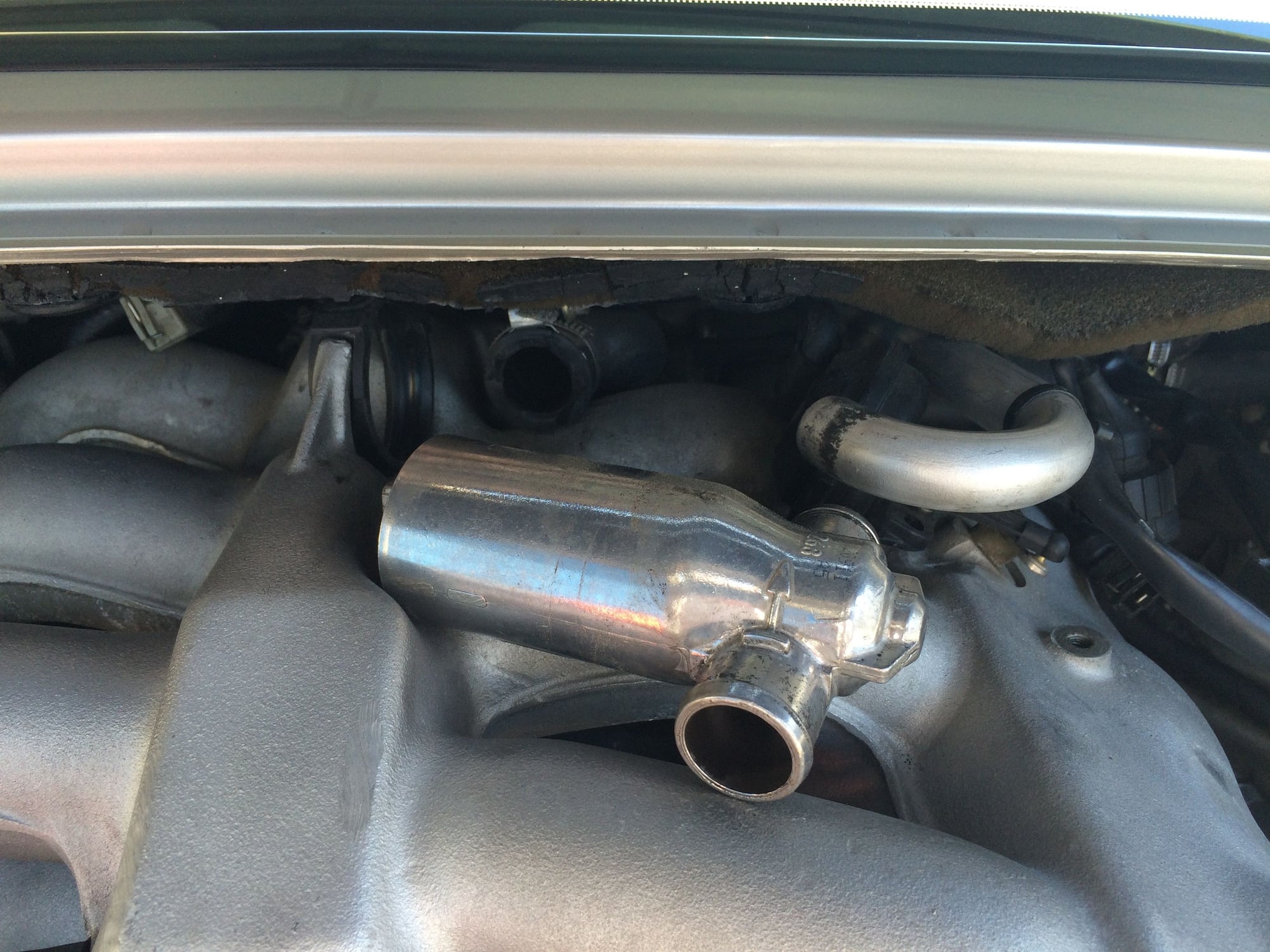
Step 5 - slide the valve to the right and remove. Push back on the hose in the
back if necessary to free the valve.
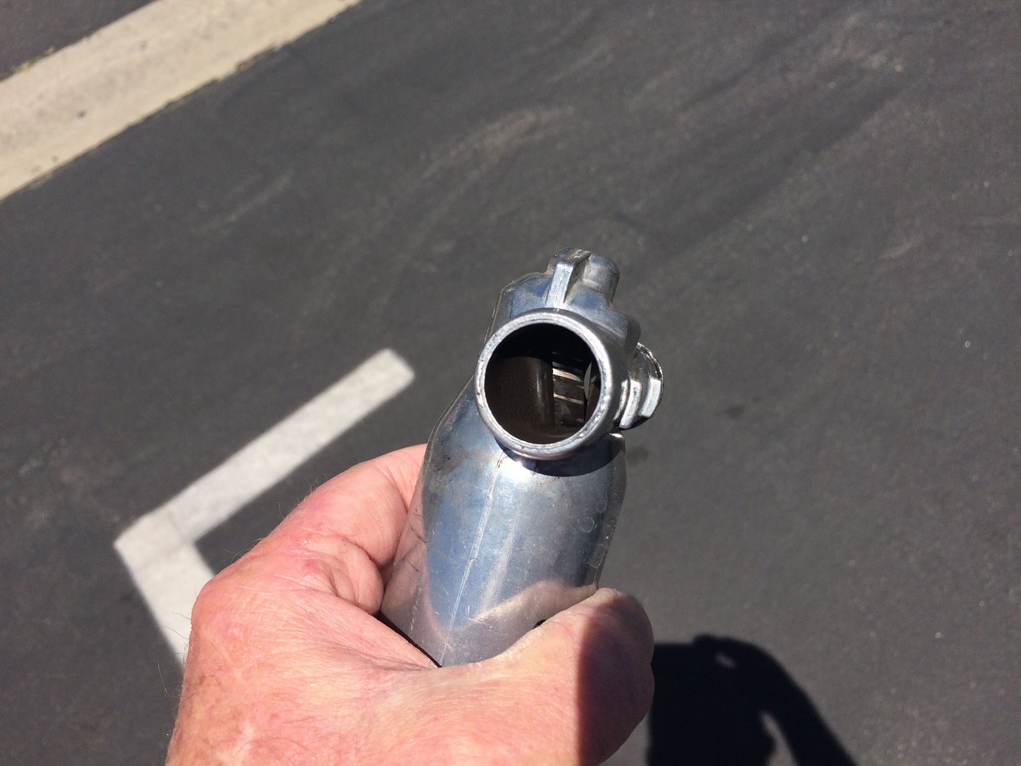
Here I have freed the valve and now it is ready to clean.
This shot shows the carbon deposits that build up in the airway.
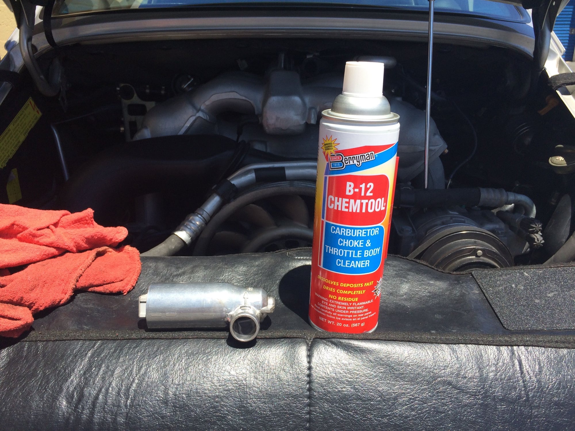
I use and highly recommend Berryman B-12 Chemtool to clean the ISV. Be sure
to use eye protection. The B-12 is powerful enough to clean the deposits on its
own but you can use a Q-Tip to assist. I was done in just a few minutes. When
it is clean it will rattle and move freely when you rotate it quickly. A little squirt
of compressed air is good to blow it out and you�re done. Should take no more
time than about 5 minutes.
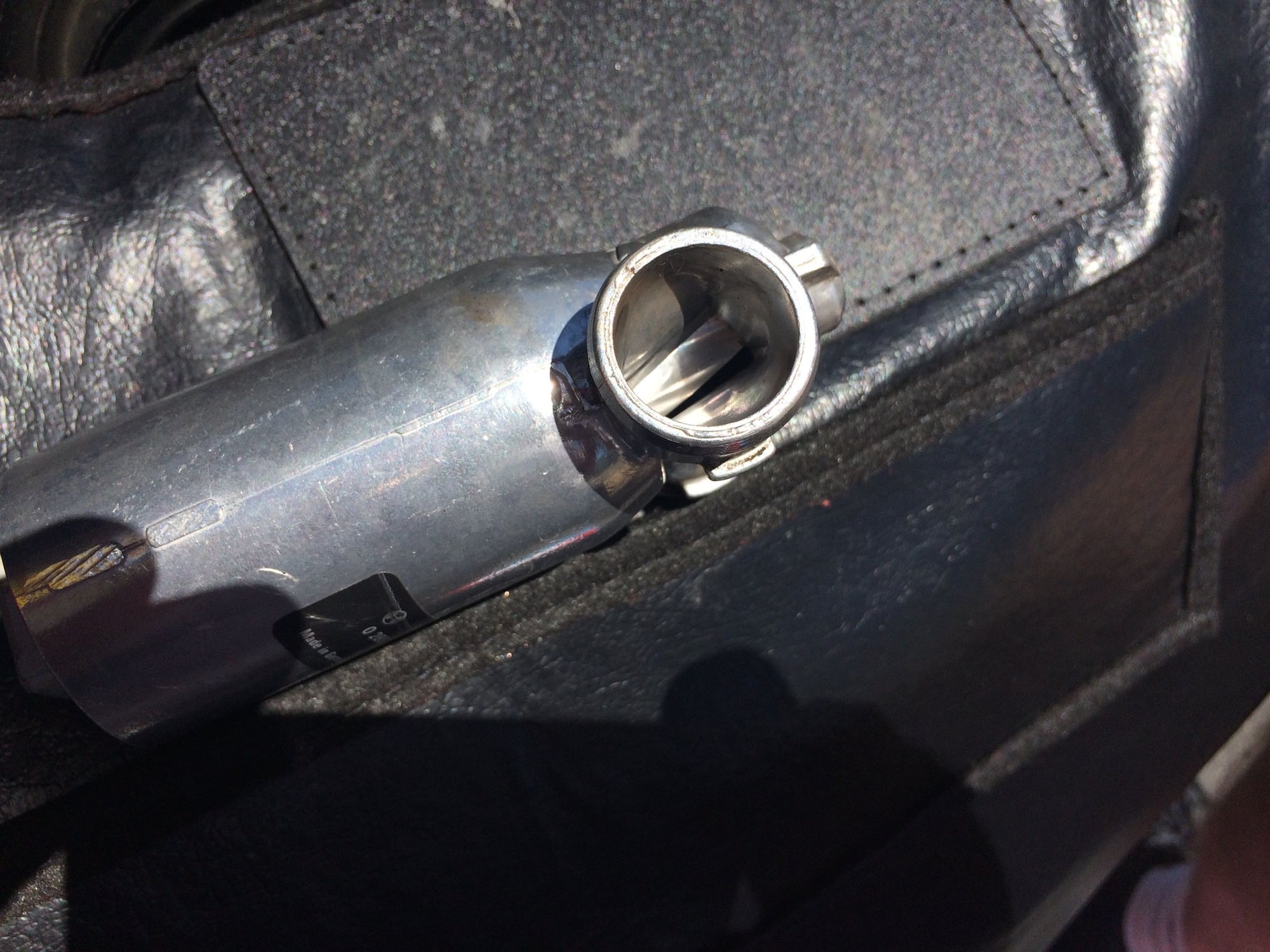
Here is the after shot showing the clean barrel of the ISV.
Installation is the reverse of removal. The only other tip I would suggest is to
lube the rubber o-ring that holds the valve before refitting. I used isopropyl
alcohol 91% and it works very well. The other rubber hose and coupling don�t
need any lube.
The ISV Theory of Operation
To control the idle speed of the engine, an idle stabilization valve (ISV) is used.
It controls the amount of air that bypasses the throttle valve.
The ISV consists of a double solenoid, one for opening and one for closing the
valve. A power supply is connected to both solenoids and the ground side of
each solenoid is connected to the DME. When the DME needs to change the
position of the valve, it activates the solenoid by switching the solenoid to ground
with a duty cycle signal, which creates a magnetic field that pulls the valve to the
new position.
The duty cycle value (ON TIME) affects the position of the valve and therefore
the amount of the air bypassing the throttle valve.
A duty cycle is the percentage of one period in which the signal is active. A
period is the time it takes for a signal to complete an on-off cycle. The duty cycle
is expressed as:
D = T /P x 100%
where D is the duty cycle, T is the time the signal is active (ON TIME), and P is
the total period of the signal. For example, a 60% duty cycle means that a signal
is on 60% of the time and off 40% of the time.
Here for example is a 50% duty cycle:
From my testing, the 993 ISV duty cycle at idle is about 35-40% for the closing
solenoid and 60-65% for the opening solenoid.
Testing the ISV
There are two parts to testing the ISV:
1. Testing the supply voltage
2. Testing the control signals
Testing the Supply Voltage
Pull off the wiring harness connector to the ISV.
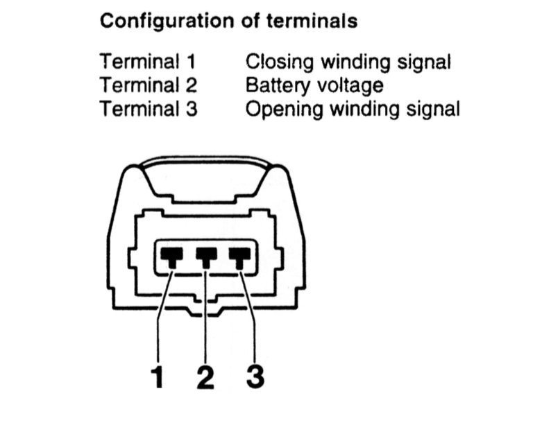
The pin assignments are shown in the diagram below from the workshop manual.
Setup a voltmeter with a ground connection back to the battery negative terminal.
Turn the key to switch position Ignition On.
Probe the middle pin of the wiring harness connector (Pin 2) and check the
voltage. It should be 12 V. If not check in accordance with the wiring diagram.
Testing the Control Signals
Connecting the Scope
In accordance with the workshop manual, I�m going to use the 3-pin adapter they
suggest which is the VAG 1501.
The wiring diagram for VAG 1501 is shown below.
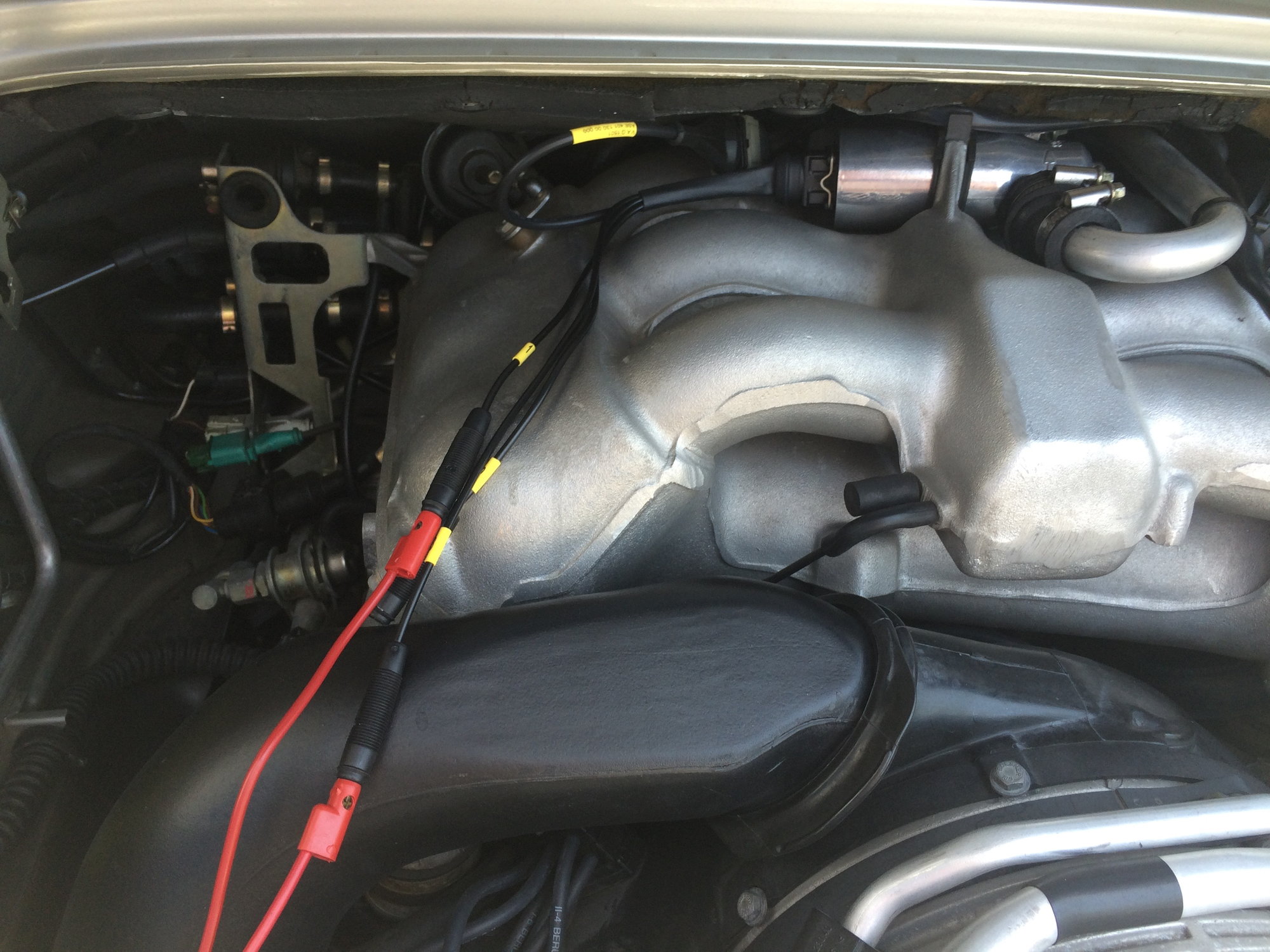
The adapter is connected between the idle stabilizer and the wiring harness plug.
Channel 1 of the scope is connected to terminal 1 (closing winding) and
Channel 2 is connected to terminal 3 (opening winding). The ground connection
for both channels is connected to the battery negative terminal.
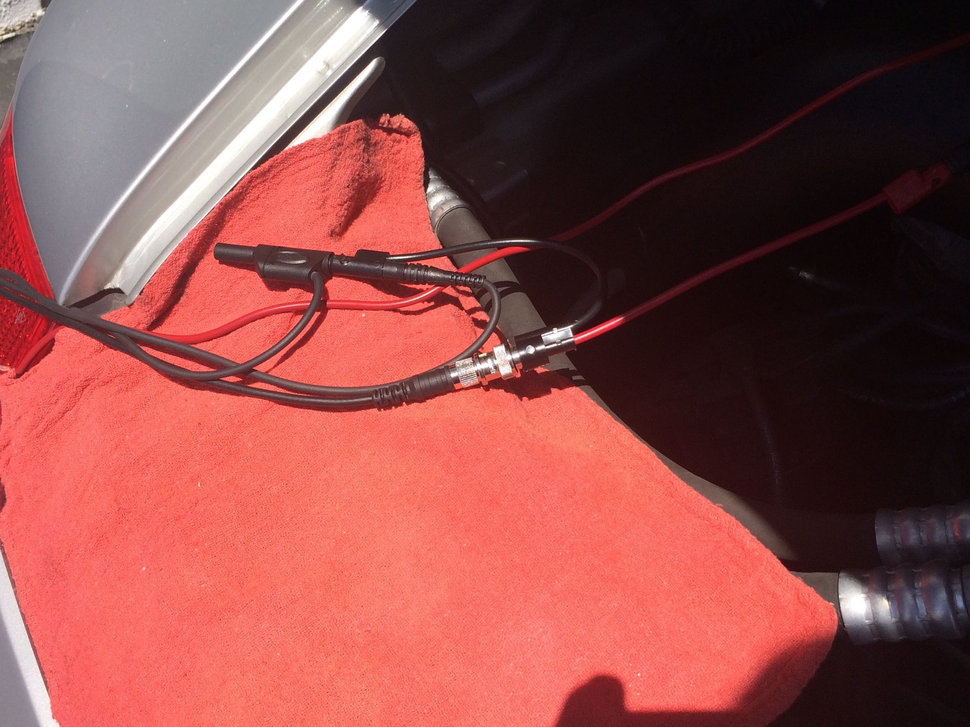
In this shot you can see that I stacked the ground connections using banana
jacks to one lead to the battery.
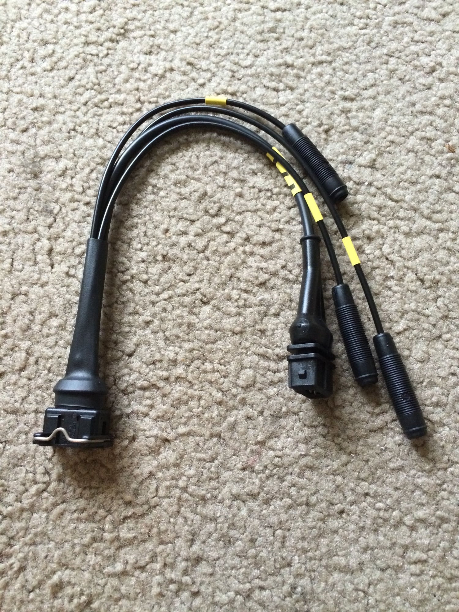
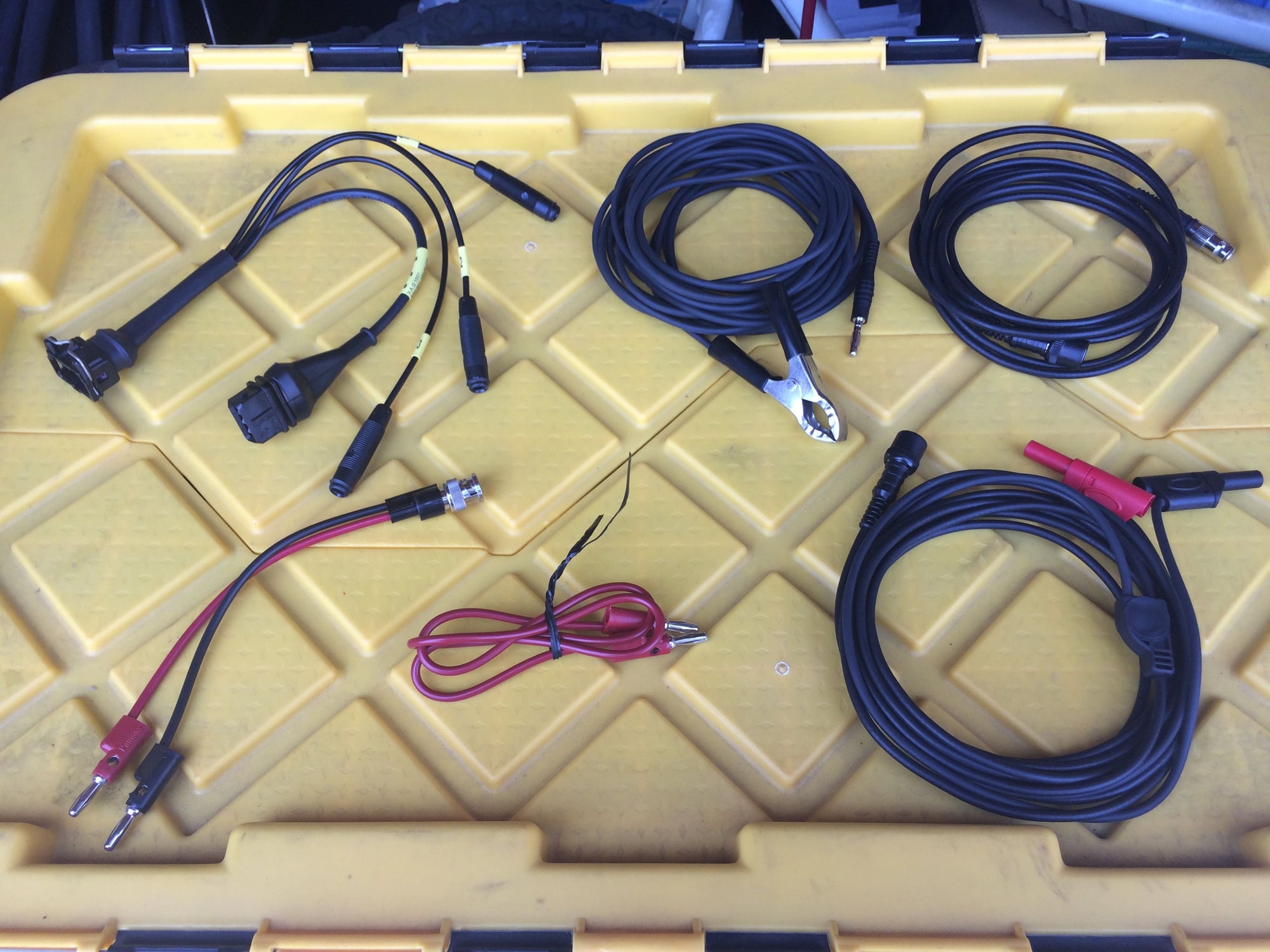
Here are all the test leads that I used to connect the scope to the ISV. Note that
the VAG 1501 only accepts non-insulated banana jacks.
Running the Tests
Startup
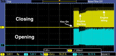
In the above capture I have started the engine and captured a few seconds of
the engine idling. Channel 1 (Yellow) shows the closing signal voltage and
Channel 2 (Blue) shows the opening signal voltage. The voltage scale
for both channels has been set to 5 V per vertical division. (The expected control
signal amplitude is 15 V). The timebase is set to 1 second per horizontal division.
I�ve setup an automatic measurement for the positive duty cycle on each channel.
Startup Zoomed
In this image I have zoomed into the waveform at the point where the key is
turned on. When the key in turned on the DME sends a signal to both opening
and closing solenoids and holds it for about 42 ms. During this time period the
DME is learning the position of the valve. The DME then sets the duty cycle signal
to a setting that matches current engine state.
A closer look at engine start
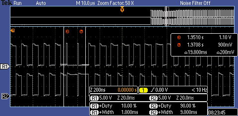
In this image I have recalled the initial capture for later analysis to take a closer
look at the duty cycle during start. Channel R1 is the closing signal and R2 is the
opening signal. In the upper area of the image you can see the location in the
overall waveform to which I have zoomed in. I placed cursors on the waveform
to gate the duty cycle measurement. The default is to gate over the entire
screen and I�m just interested in this narrow region. Between the cursors we can
clearly see a large difference between the closing and opening signals. This is
because during engine start the DME increases the duty cycle to allow the intake
of air. Thus the duty cycle for the closing signal is 10.00% and the opening signal
is 90.00%. The pulse width for the closing signal is 1 ms and the pulse width for
the opening signal is 9 ms. Subsequently, the DME adjusts the duty cycle to
stabilize the engine to the correct idle speed.
Idle
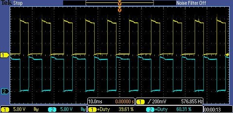
In the above image, the engine is idling. The duty cycle for the closing signal
is 36.68% and the opening signal is 63.24%. The signal amplitudes are 15 V
peak. The closing pulse width is about 4 ms and opening pulse width is about
6 ms.
This is a good waveform and indicates correct operation of the ISV.
To see how the ISV behaves under various loads and rpm a few more tests were made.
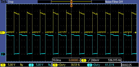
A/C on at idle
In the above image, the engine is idling with the A/C on. The duty cycle for the
closing signal is 39.61% and the opening signal is 60.31%. The signal amplitudes
are 15 V peak. The closing pulse width is about 4 ms and opening pulse width is
about 6 ms.
Engine at Idle with headlights, foglights, radio, rear defroster on
In the above image, the engine is idling with some accessories turned on
(low beam headlights, foglights, radio, and rear window defroster). The duty
cycle for the closing signal is 38.59% and the opening signal is 61.33%. The
signal amplitudes are 15 V peak. The closing pulse width is about 4 ms and
opening pulse width is about 6 ms.
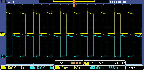
Engine 2000 rpm
In the above image, the engine is raised to 2000 rpm. The duty cycle for the
closing signal is 44.00% and the opening signal is 55.92%. The signal amplitudes
are 15 V peak. The closing pulse width is about 4 ms and opening pulse width is
about 6 ms.
Diagnosis
The following signal conditions can indicate a problem:
1. No signal
Possible causes: poor test lead connections, no supply voltage, ISV defective,
DME defective.
2. Low signal voltage (< 15.0 V)
Possible causes: poor test lead connections, low supply voltage, poor DME ground,
ground side resistance in wiring to DME.
3. Noisy signal
Possible causes: supply voltage or signal wiring damaged, poor connector
terminals, defective ISV.
4. Signal offset
Possible causes: scope not set for DC coupling, poor supply voltage, poor DME
ground, ground side resistance in wiring to DME.
If the supply voltage is correct and the control signals are correct, yet the engine
will not idle, then replacement of the ISV is indicated.
NOTE: Before condemning the ISV, check the throttle body for carbon
deposits.
Complaints associated with a dirty throttle body are: deceleration stalling,
start-stall, stalls at stops, always restarts, will not stall if one foot is kept
on the gas.
The throttle body should be cleaned with a small brush or rag and carb cleaner
for any of the above complaints, before any further diagnosis is done on an idle control system.
Checking and fixing any other deferred maintenance items such as vacuum leaks,
cleaning the MAF sensor, cleaning the fuel injectors, checking the O2 sensors and
the rpm sensor and cleaning the grounds, especially at the battery and under the
drivers seat should be made as well.
Thank you Steven! I'm using a Tektronix DPO2002B. It's not designed for
automotive use but I'm able to do just about everything I've wanted to do
so far.
Originally Posted by phoneyman
Your DIYs are always top notch, but you really outdid yourself on this one. Good job and thanks!
Thank you Phoneyman! This was a very interesting DIY to research and do.
My aim over time is to visit all of the DME sensors and electronics and learn
what I can about them with the
aid of the scope.
Is it normal for the IACV / ISV to run hot? I noticed mine runs pretty hot, so hot that i can barely keep my fingers on it for ~5 seconds when I'm "bench" testing it with the motor off and an stand alone engine management system controlling the valve.
Great write-up! Very comprehensive and educational. Adding it to my 993 procedures folder, well done!
Shade Tree mechanic weekend man's valve testing, not perfect but seems Ok as part of the cleaning process:
Detach the valve from its hoses and electrical connection;
Clean the electrical plug and socket with spray electronics cleaner, dare I say the CRC brand?
Clean the valve internals with choke cleaner spray;
Verify after cleaning that the valve seems to float between its open and closed position and when twisted in your hand it freely rocks like on a spring back and forth;
Apply 12 volts+ to the common (middle pin) pin and negative to one of the other pins for a moment and verify that the internal valve snap to a fully closed or open position;
Apply 12 volts+ for a moment to the common pin and negative to the other pin not used above and verify that the internal valve snap to the opposite position to the above;
Reassemble the valve to its hoses;
Plug the valves wiring harness plug back in making sure the sealing gasket inside the plug is in the correct position and the plug fully seats.
This doesn't check for the valve receiving the proper signal but it addresses functional issues with the valve itself that are usually the cause for idle problems associated with the valve.
Andy
Great write-up! Very comprehensive and educational. Adding it to my 993 procedures folder, well done!
Shade Tree mechanic weekend man's valve testing, not perfect but seems Ok as part of the cleaning process:
Detach the valve from its hoses and electrical connection;
Clean the electrical plug and socket with spray electronics cleaner, dare I say the CRC brand?
Clean the IS valve internals with choke cleaner spray;
Verify after cleaning that the valve seems to float between its open and closed position and when twisted in your hand it freely rocks like on a spring back and forth;
Apply 12 volts+ to the common (middle pin) pin and negative to one of the other pins for a moment and verify that the internal valve snap to a fully closed or open position;
Apply 12 volts+ for a moment to the common pin and negative to the other pin not used above and verify that the internal valve snap to the opposite position to the above;
Reassemble the valve to its hoses;
Plug the valves wiring harness plug back in making sure the sealing gasket inside the plug is in the correct position and the plug fully seats.
This doesn't check for the valve receiving the proper signal but it addresses functional issues with the valve itself that are usually the cause for idle problems associated with the valve.
Andy
Andy,
I have no axe to grind with the CRC brand, but when I see you continuously recommend using Electronics cleaner on items that need to be cleaned with a carb and or choke cleaner, it makes me cringe...
Especially, after you having found corrosion in your ISV from using your favorite CRC electrical contact cleaner!
Thank goodness you are now referencing the correct cleaner for the respective component, as bold-faced above.
Bruce has it right in his DIY, and he's head and shoulders above my knowledge base!
FYI for those newer members. Bruce7 has authored a whole slew of excellent DIYs on the board over the years. They are often the most comprehensive you'll find anywhere. It's worth searching Google like this to find them - "site:rennlist.com bruce7 ISV Valve" for example.
Also, I may be imagining things, but I thought I read that Bruce7 sold his car to Tlaloc75. If so, his car lives on at Rennlist with another enthusiast...
Yes that�s right.
I get a kick out of reading these old diy threads to see what he did with the car before my ownership. It�s an online maintenance record of sorts.
I can only hope that I live up to his example as a great steward so that I may preserve the car for the next owner (or generation) to enjoy as much as I have.
Thank goodness you are now referencing the correct cleaner for the respective component, as bold-faced above.
You do not want to use brake cleaner, carb cleaner, xylene, tolulene (aka. carb cleaner), methanol, MEK, acetone (aka brake cleaner) on the ISV which is nothing more than an unsealed electric motor. Stick with rubbing alcohol and a q-tip or you will end up having to replace it.
You do not want to use brake cleaner, carb cleaner, xylene, tolulene (aka. carb cleaner), methanol, MEK, acetone (aka brake cleaner) on the ISV which is nothing more than an unsealed electric motor. Stick with rubbing alcohol and a q-tip or you will end up having to replace it.
Jason,
I follow your posts and I greatly respect your knowledge and opinion; however in this case, I respectfully disagree...
Anything that would introduce fibers, such as a Q-tip would be a huge no-no in this application.
There are bronze or brass bearings that the butterfly pivots within and any introduction of a fibrous material would be detrimental to the smooth effective operation of the butterfly.
The carb and choke cleaners mentioned will dissolve and eliminate the soot and coking, for lack of a better term, that builds up and hampers the proper operation of the butterfly valve.
At the same time, the formulation contains very light lubricants without completely drying the bearing pivot points or introducing water, which is a significant percentage of rubbing alcohol.
 05-31-2016, 03:34 PM