When you click on links to various merchants on this site and make a purchase, this can result in this site earning a commission. Affiliate programs and affiliations include, but are not limited to, the eBay Partner Network.
I manage to get by with my knowledge of wiring, but my knowledge of current and what it does still needs some work. One Day!!
Thank you Steven! After reading about your incredible build project I think
you would really enjoy working with a scope. I have been teaching myself
how to use it and the 993 offers so many possibilities to learn diagnostics and
how the car works.
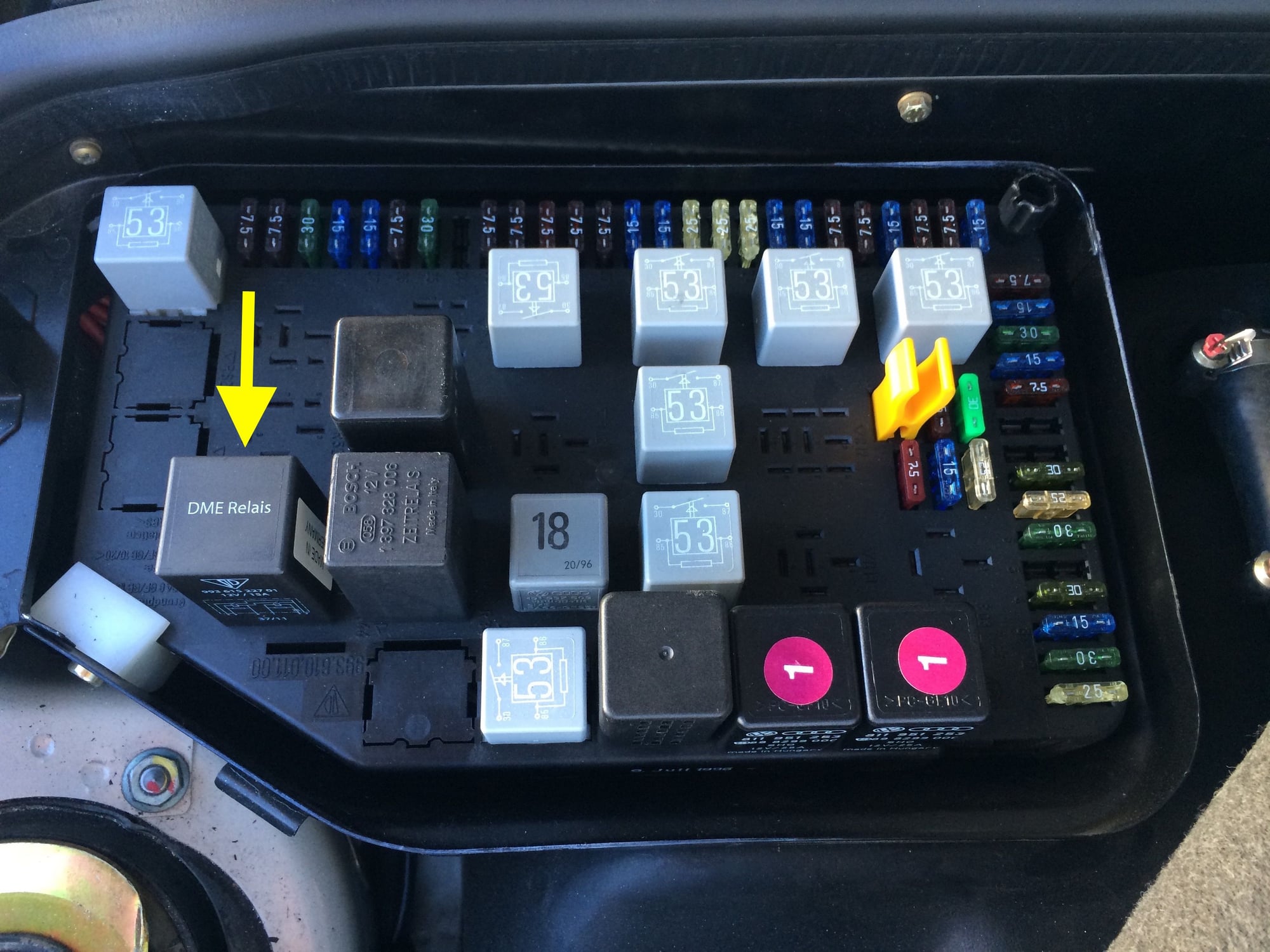
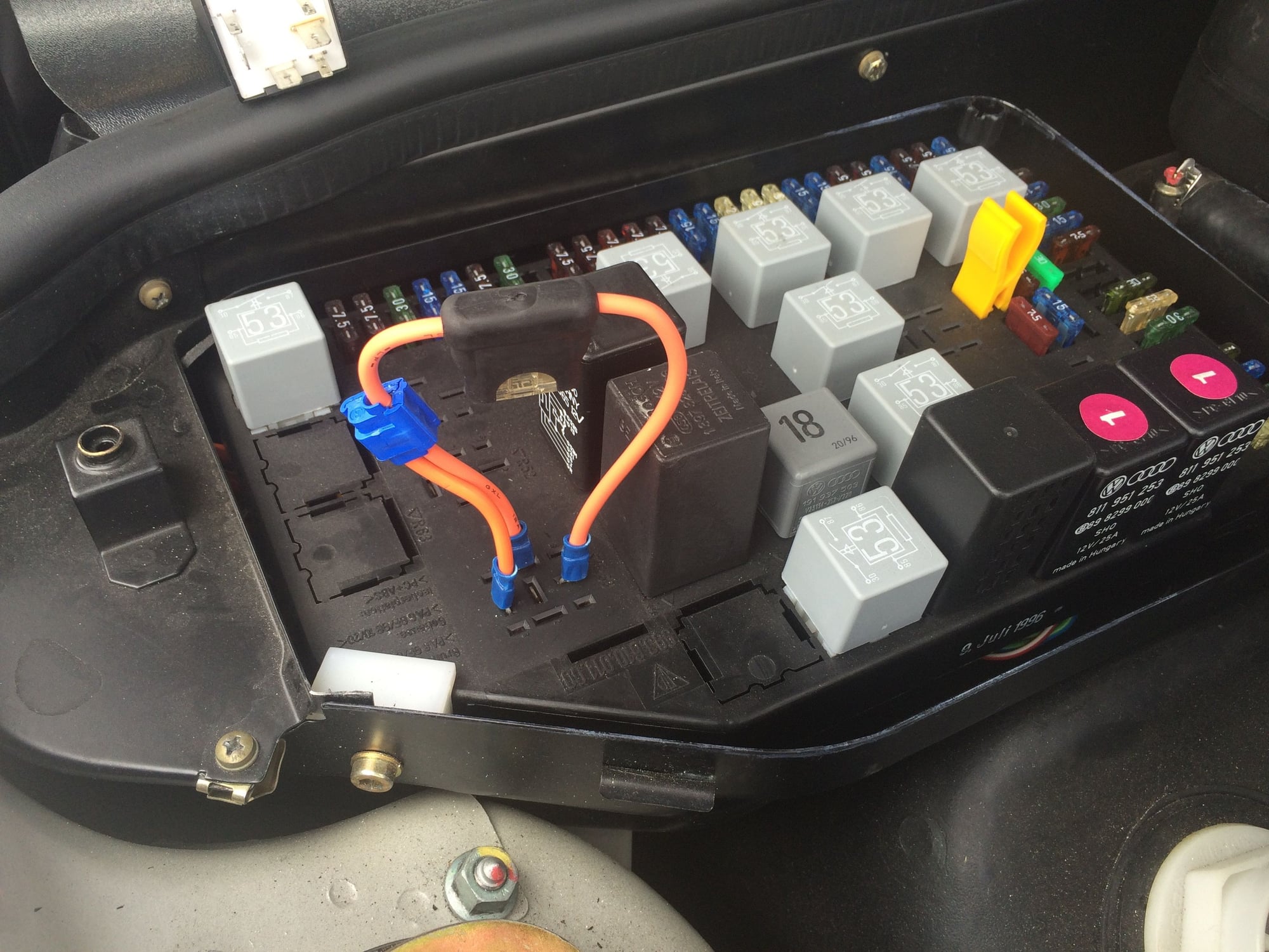
The DME relay (R53) is located in the fuse panel in the luggage compartment
shown in the photo below:
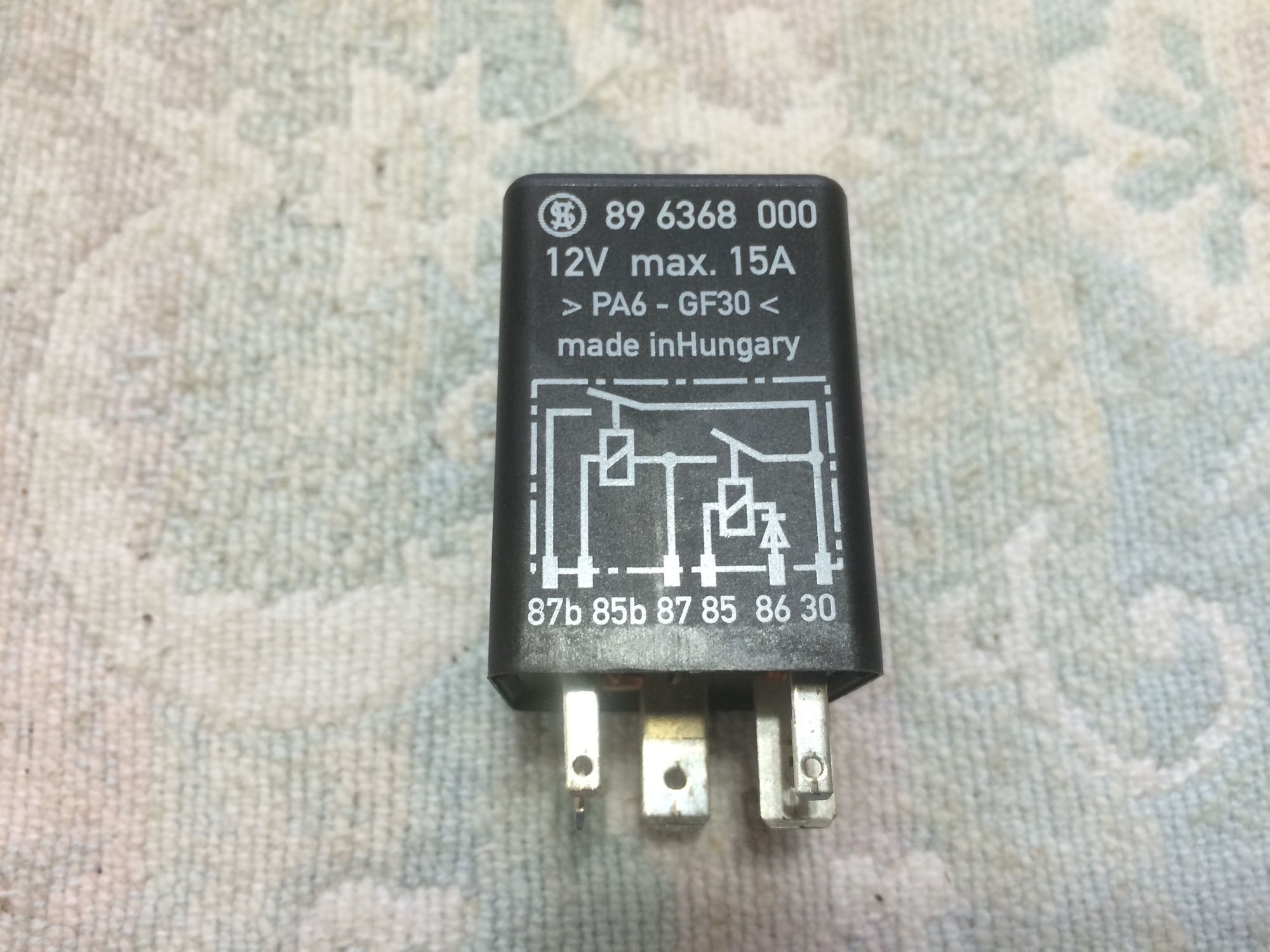
The 993 was originally equipped with a 944 DME relay (944-615-227-00).
The 944 part was later replaced with a 993 part and the current version is
993-615-227-01.
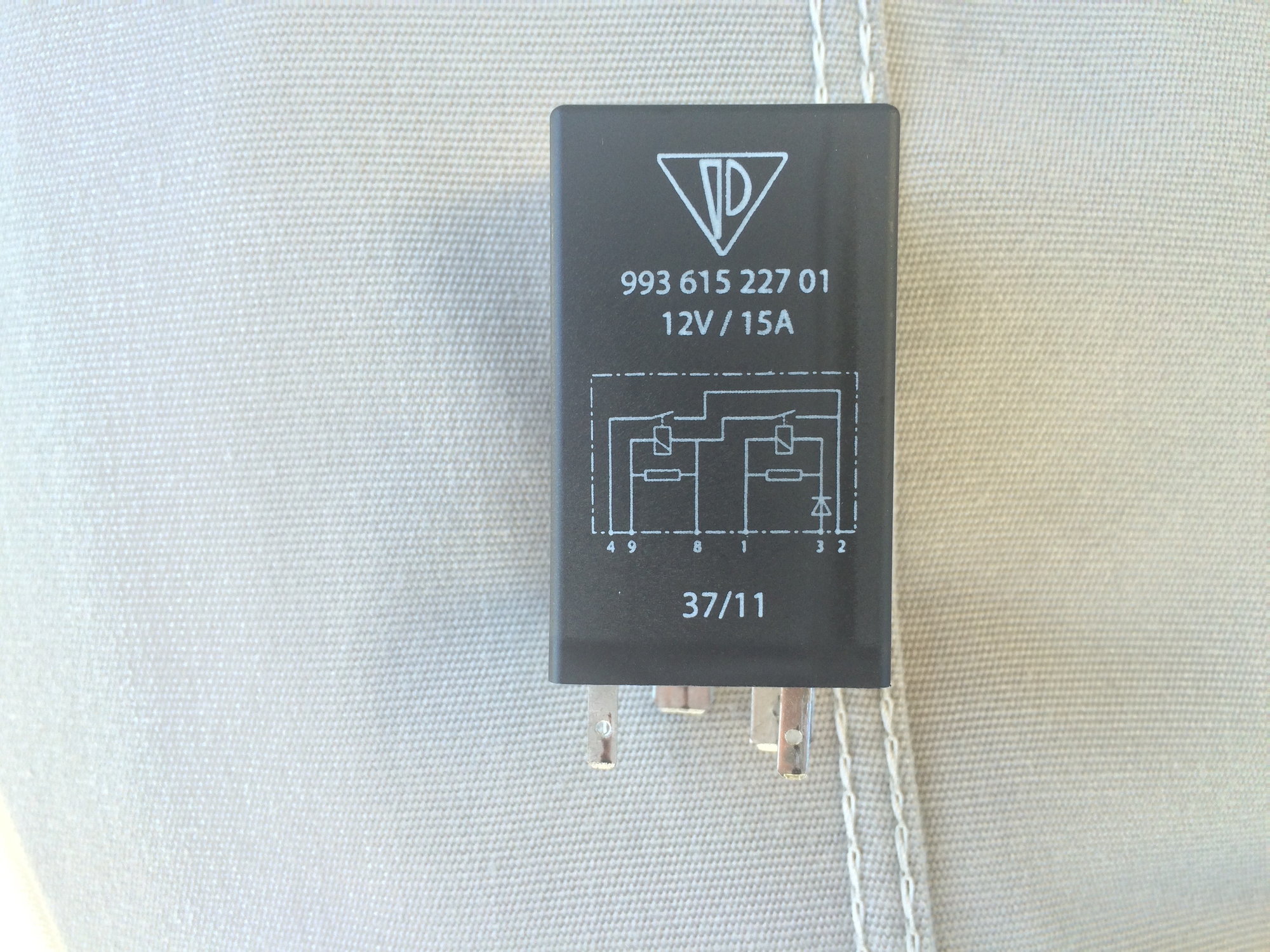
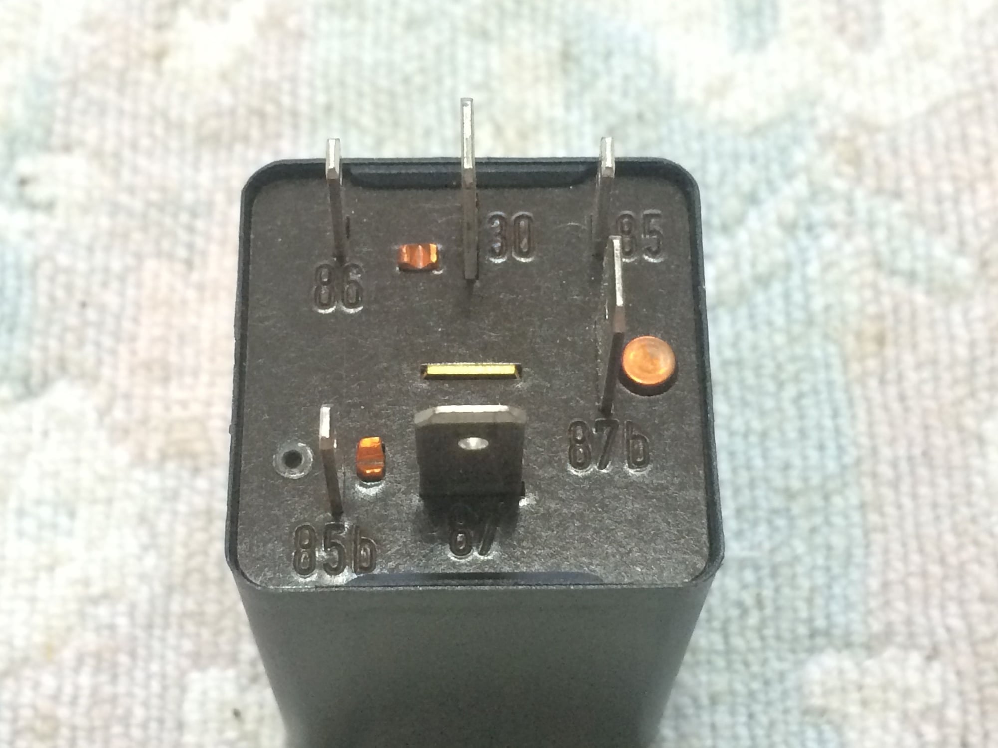
The wiring for the relay is imprinted on the side of the relay. As you can see
the older relay used DIN terminal designations and the later relay uses numbers.
This can cause confusion when comparing the fuse panel designations with the
relay designations with the Sheet 5A or Sheet 5B wiring diagrams.
For a refresher on DIN designations, see the attached article �Understanding
European DIN Wiring�.
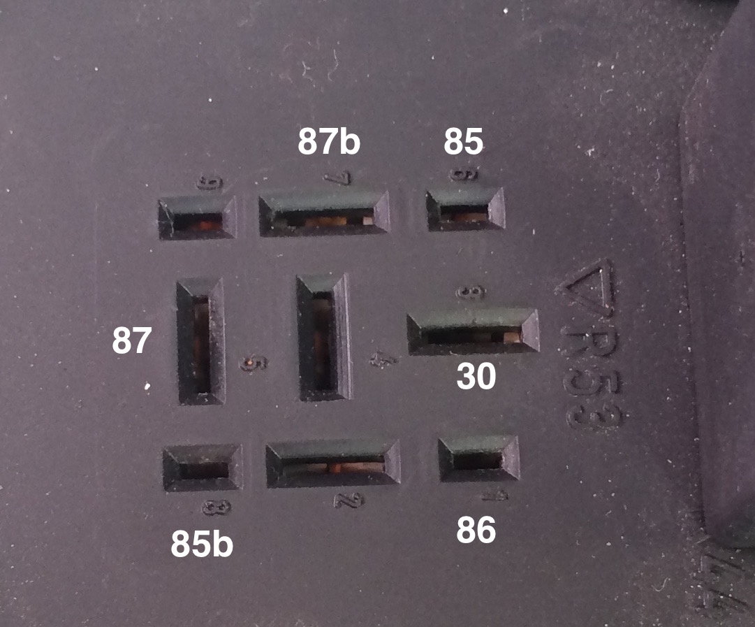
Here is a closer look at the fuse panel terminal designations molded into the
plastic panel for R53:
The wiring diagram matches the fuse panel designations. The numbers on the
993-615-22701 relay do not match the wiring diagram or the fuse panel
designations. They only match the numbers on the bottom of the relay. So be
careful when testing using these terminals.
Another interesting observation between the older and newer relay is that the
newer relay incorporates de-spiking resistors for both coils to suppress voltage
spikes. For an short overview of the issue with voltage spikes and relays, see
the article by Kevin R. Sullivan titled �Understanding Relays�, pages 11-13: http://www.autoshop101.com/forms/hweb2.pdf
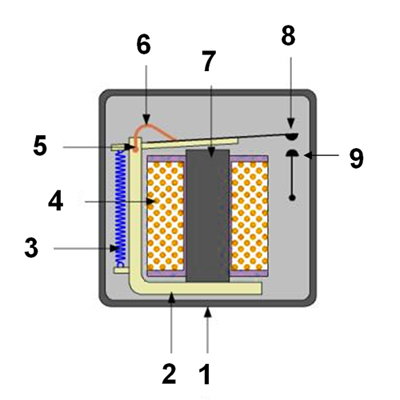
1. Housing
2. Pole piece
3. Return spring
4. Copper coil
5. Hinge
6. Flexible copper braid
7. Soft iron core
8. Movable electrical contact
9. Non-movable electrical contact
The way a relay works is a low level input current is switched through the coil,
building a magnetic field, which then pulls the movable contact to the fixed
contact, completing a circuit and allowing a higher current to flow to the load.
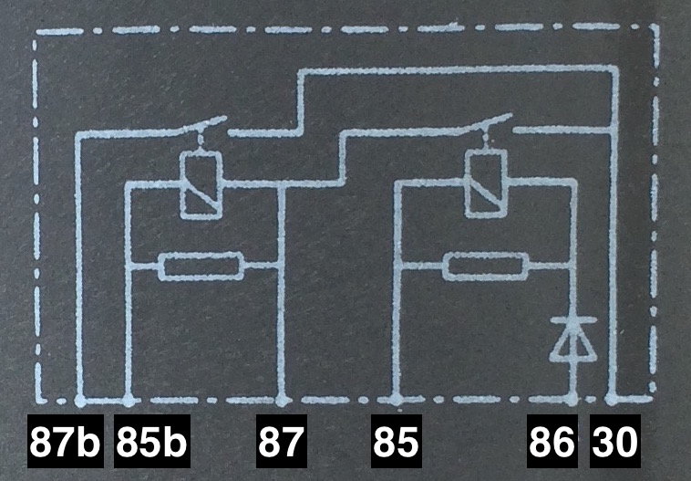
The Function of the DME Relay
The DME relay is a double-pole, normally open relay which is used to enable
two main functions: fuel injectors and fuel pump.
In the image above, I took the diagram from the side of the 993 relay and
overlaid the DIN designations to help guide a big-picture view of what the DME
relays does.
I find it helpful to think of the relay circuits in terms of the power side, the
control side and the load side.
Power side: terminal 30 - hot all the time, wired straight to the battery
Control side(s): terminals 85 and 85b - grounds controlled by the DME
Load side(s): terminal 87b - power to fuel pump, MAF and O2 sensor heaters
terminal 87 - power to fuel injectors and several DME electronics
When the DME grounds terminal 85, the coil closes the contact and current flows
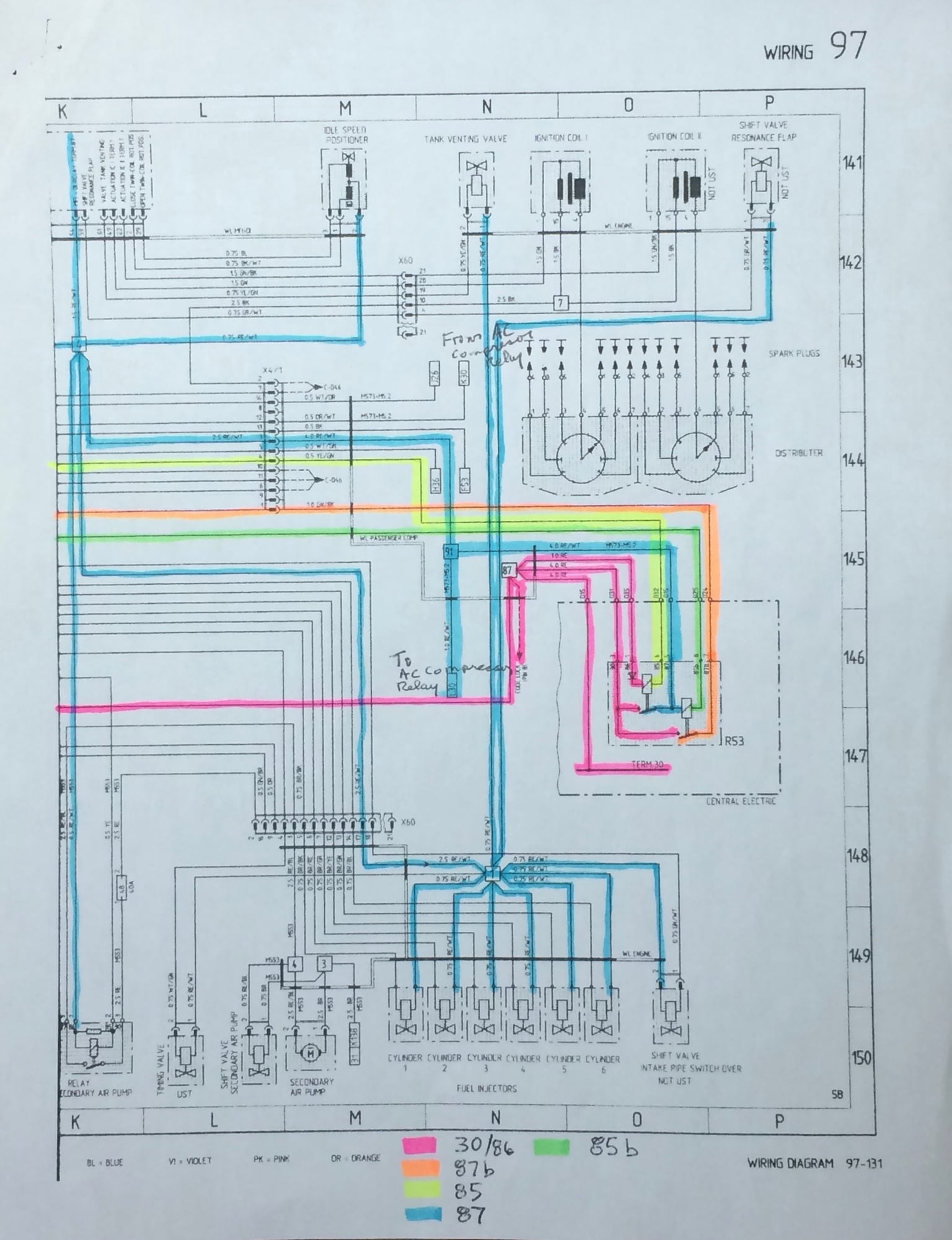
via terminal 87 to power the fuel injectors and the DME electronics. See the blue
trace on the wiring diagram below.
When the DME grounds terminal 85b, that coil closes the contact and current
flows via terminal 87b to the fuel pump, the MAF sensor and the oxygen sensor
heaters. See the orange trace on the wiring diagram below.
Point to remember: with the DME relay removed, the car will crank but will not
start.
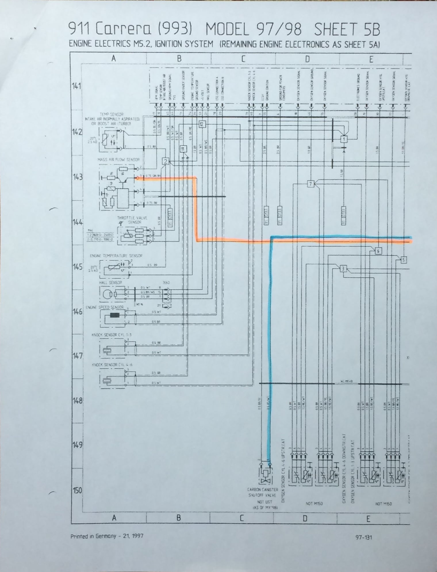
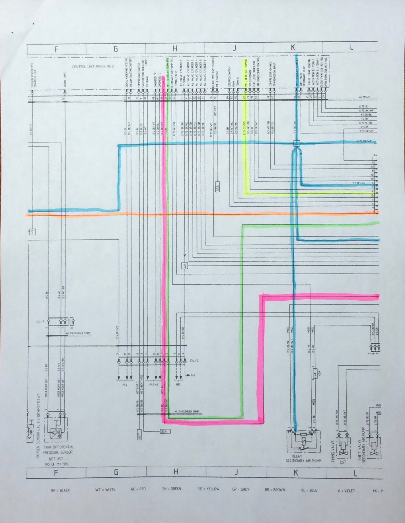
Ignition System Wiring for DME 5.2 Systems
In the previous section on electrical testing the fuel pump, the Sheet 5A wiring
diagram was presented to show the wiring connections pertaining to the fuel
pump. If you�ll notice at the top of the sheet 5A it says that it pertains to DME
2.10. What Porsche did was use Sheet 5B to cover the DME 5.2 ignition system
and redirect you to Sheet 5A for the remaining engine electronics. For example,
on the 97 model, both sheets 5A and 5B must be referred to.
Sheet 5B is shown below broken into 3 pages and color traced.
Testing the DME Relay
Visual Inspections
Although there can be more than one way a relay can fail, on the 993, the typical
DME relay failure mode is cracked solder connections. For some excellent photos
of the internals of the DME relay check out RL member IXLR8�s webpage:
Resoldering the connections generally will restore the relay to like-new service.
When you pull the DME relay out of the fuse panel, look at the terminals for any
signs of overheating, corrosion, etc that will indicate issues that need to be
addressed. Overheating could be due to the fuel pump failing and drawing large
amounts of current or arcing. The relay contacts may also be pitted or welded
together.
The DME relay can be tested during operation and it can be removed from the
car for bench testing as well. One other interesting test is the ByPass Test.
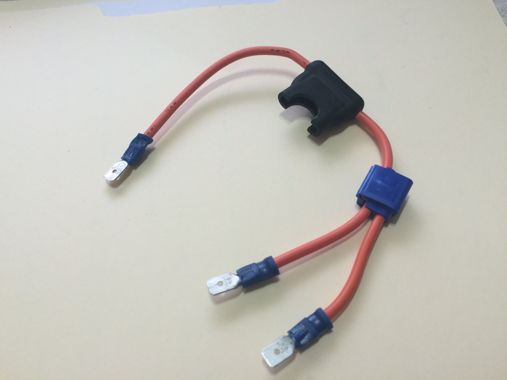
The ByPass Test
The DME relay can be bypassed using a shop-made jumper.
To use the jumper, remove the DME relay and insert a spare fuse into the jumper.
Insert the 3 legs of the jumper into the terminals 30, 87 and 87b. The unspliced
leg is the power side leg and goes into terminal 30. The two load side legs go in
87 and 87b.
The fuel pump will begin running and the engine should start using the key as usual.
This really should only be used for testing, but it can also be used as an
emergency replacement for the DME relay. Remember to remove it when done
driving or it will run down the battery.
Bypassing the control side circuits is a good troubleshooting technique to know
that can be applied to all relays. The starter relay is another good example
where this technique can be used.
In-Car Testing
With the engine running, measuring the voltage drop at the DME relay will
indicate if there are any resistance issues in the power side circuit, either with
the DME relay itself or between the DME relay and the battery.
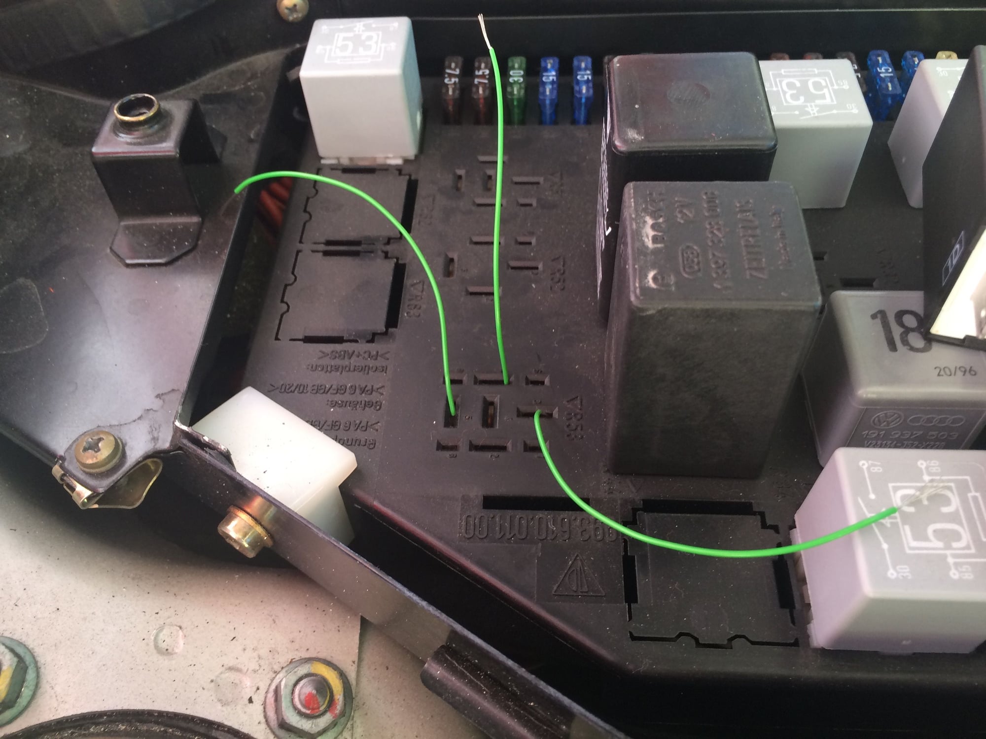
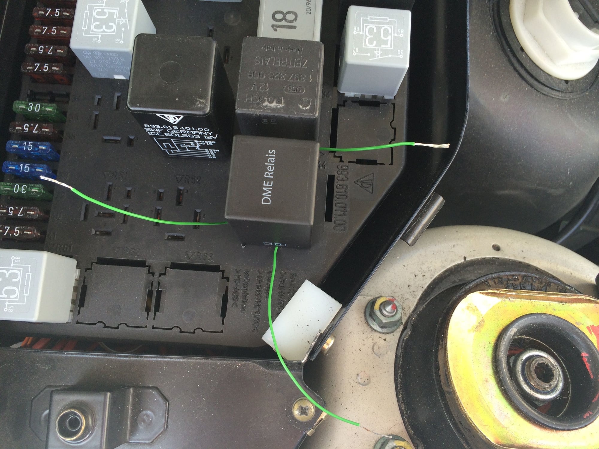
To facilitate this test, the kluge wire trick, introduced in the fuel pump test, will
be used.
The DME relay is removed and three kluge wires are placed into terminals 30, 87
and 87b.
The DME relay is then pushed down into the socket and seated.
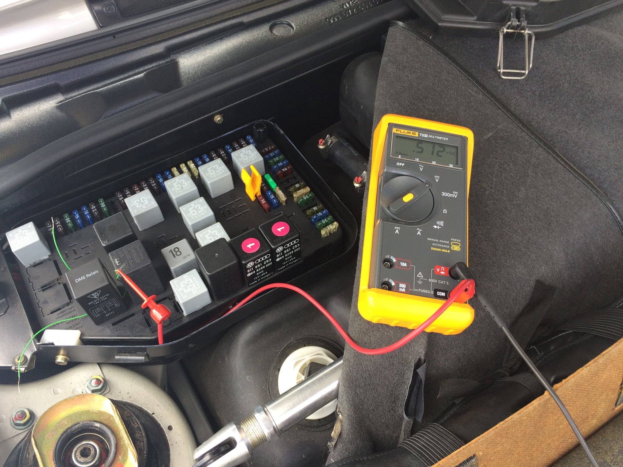
The following power side voltage drops were measured with the engine running:
B+ to Terminal 30
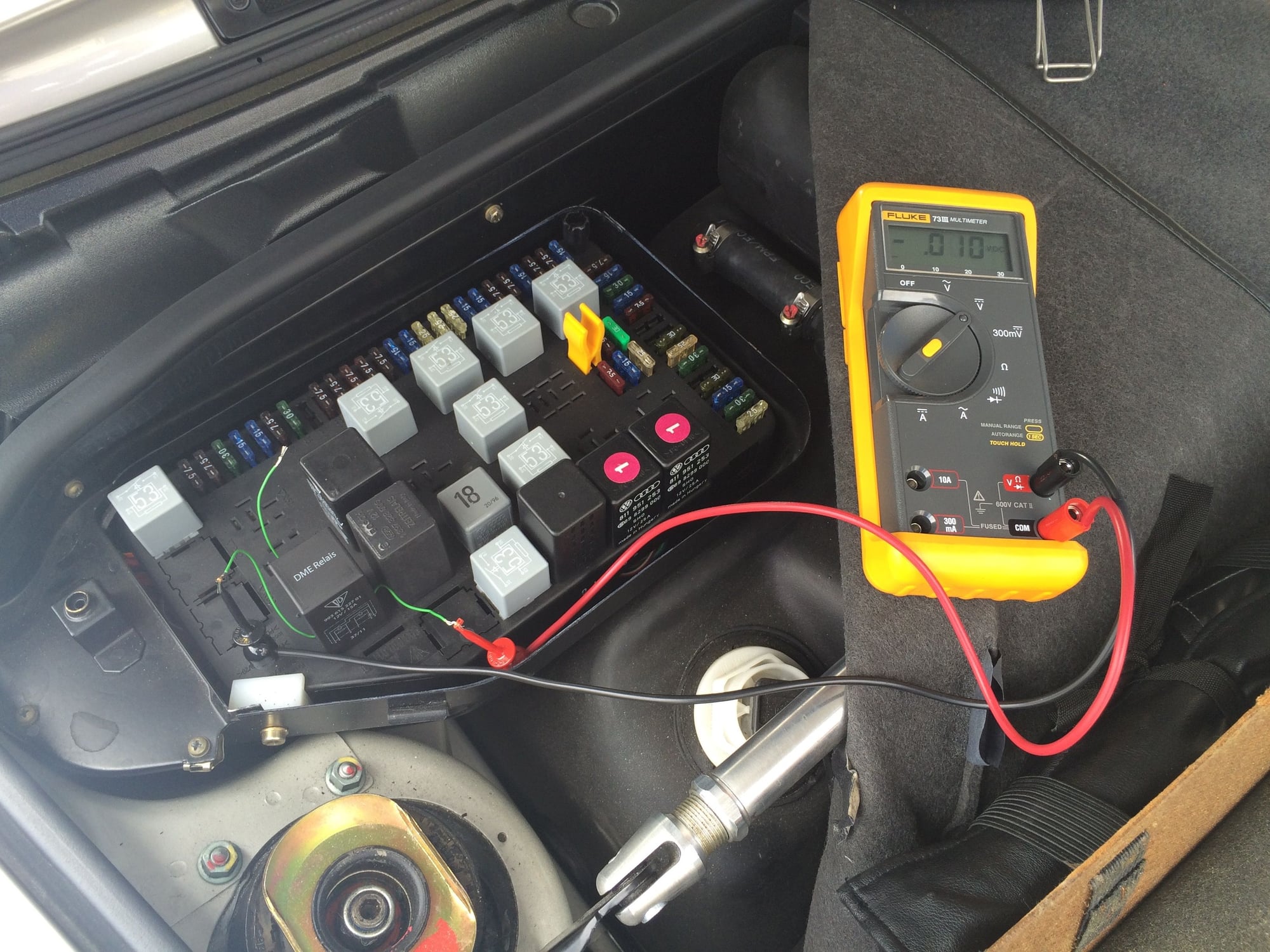
Terminal 30 to 87
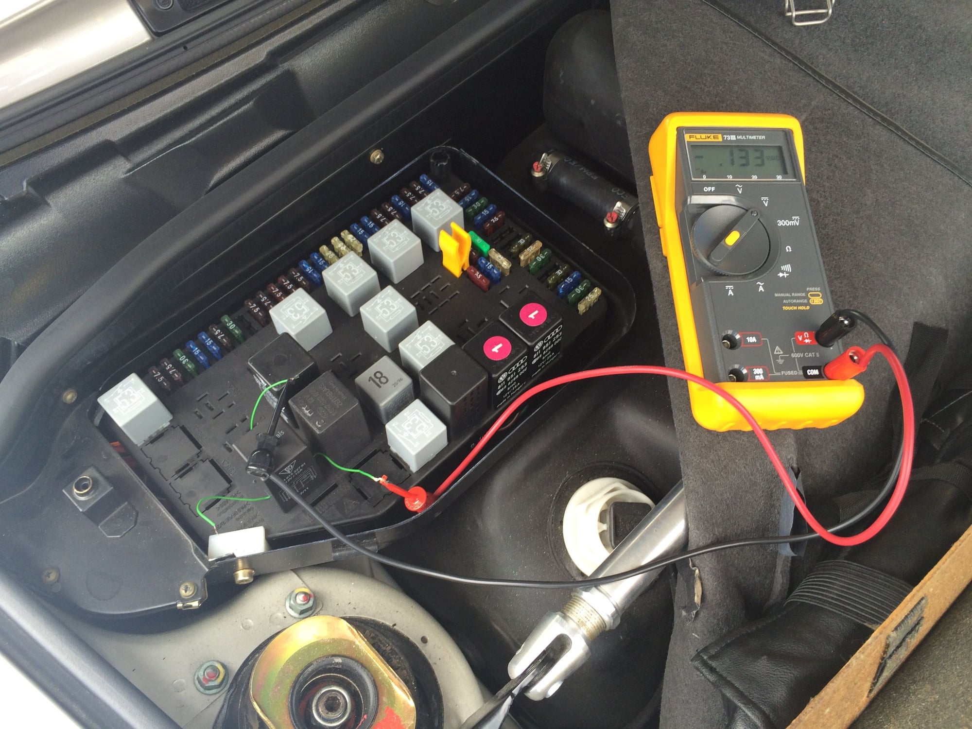
Terminal 30 to 87b
Testing Voltage Drop B+ to Terminal 30 measured 0.512 V
Testing Voltage Drop Terminal 30 to 87 measured 0.010 V
Testing Voltage Drop Terminal 30 to 87b measured 0.133 V
Remember that the voltage drop is dependent upon the load and the circuits must
be energized when doing the voltage drop test.
A large voltage drop across the DME relay would indicate a bad relay. These test
results are small and that is good.
Is the approximately 1/2 V voltage drop from the battery positive terminal to the
DME relay terminal 30 in line with expectations? I think so. It all depends upon
what the engineers designed for based upon current load, length of conductors,
size of conductors, system voltage and the number of connections and switches if any.
Acceptable voltage drop is often specified as a percentage of the system voltage.
If I use 14 V as the system voltage, then 0.5/14 = 0.0.357 or 3.6%. That is
probably an ok number. Using larger diameter wire could lower the number, but
there are always tradeoffs to be made.
Looking at the wiring diagram, there are no switches in the path from terminal
30 to the battery, so other than checking the battery positive terminal for
tightness and corrosion, this is as good as it is going to get. And from the
previous testing of the fuel pump, I know I�m getting 13.4 V to the pump which
is perfectly fine.
Bench Testing
Remove the DME relay from the car and perform the following series of tests.
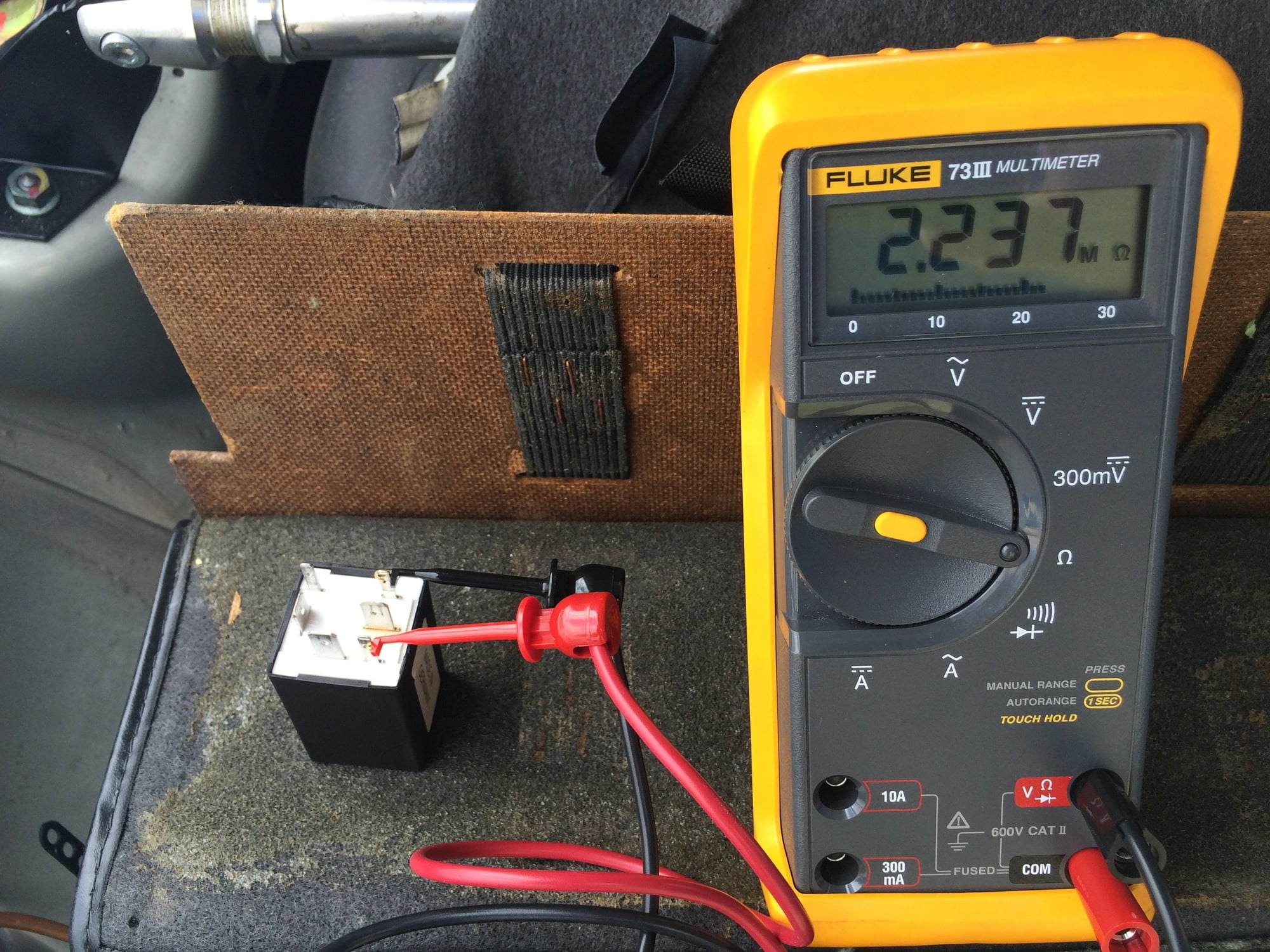
Measure the coil resistance between terminals 85 and 86.
I measured 2.237 Mega-ohms. Specs couldn't be found to compare.
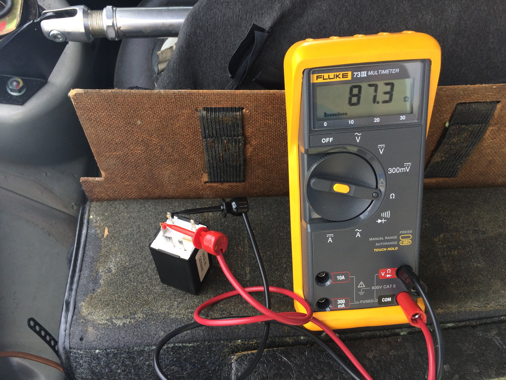
Measuring the coil resistance between terminals 87 and 85b.
I measured 87.3 Ohms. Specs couldn't be found to compare.
NOTE: for the following tests I will be using my 944 DME relay spare.
Here is what the bottom looks like which clearly shows the DIN designations.
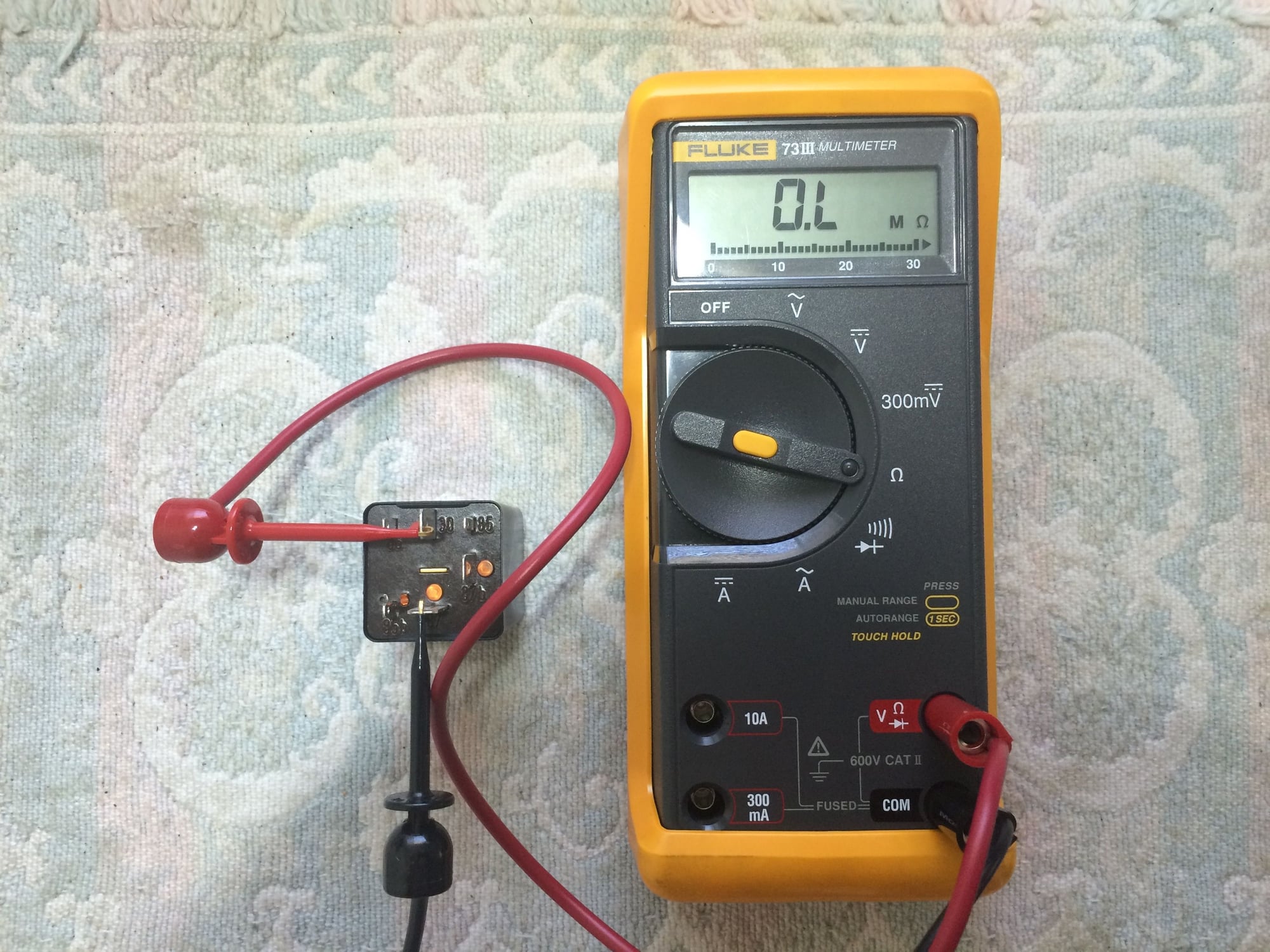
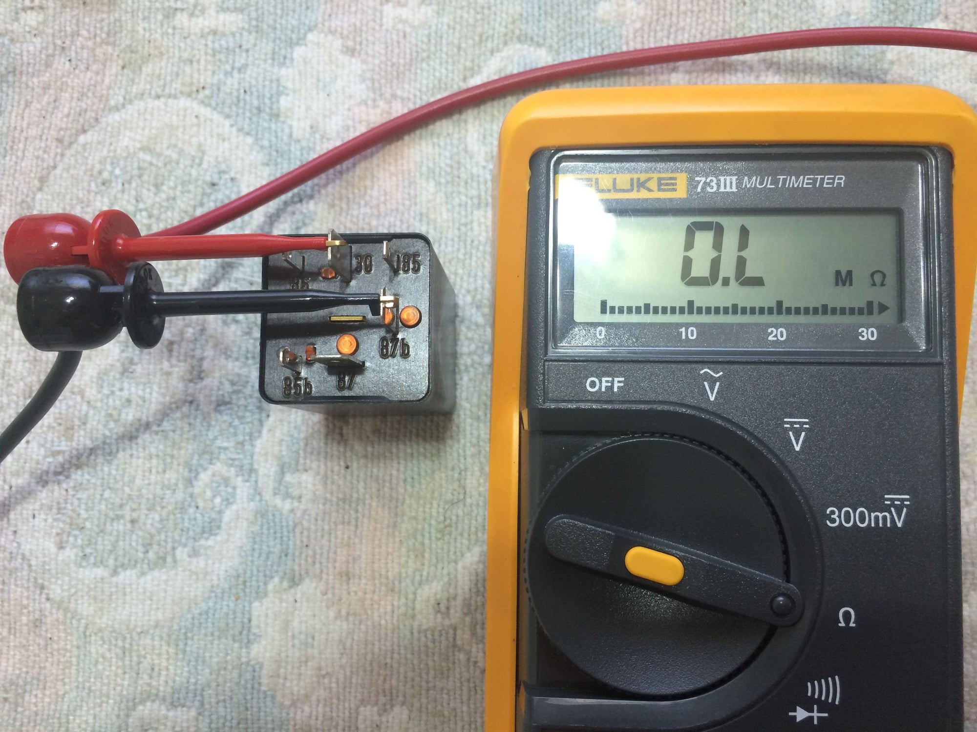
Check that there is an open circuit (infinite resistance) between terminals
30 to 87. (The Fluke meter will display OL for Open Loop if an open circuit is
detected.)
Check that there is an open circuit between terminals 30 to 87b.
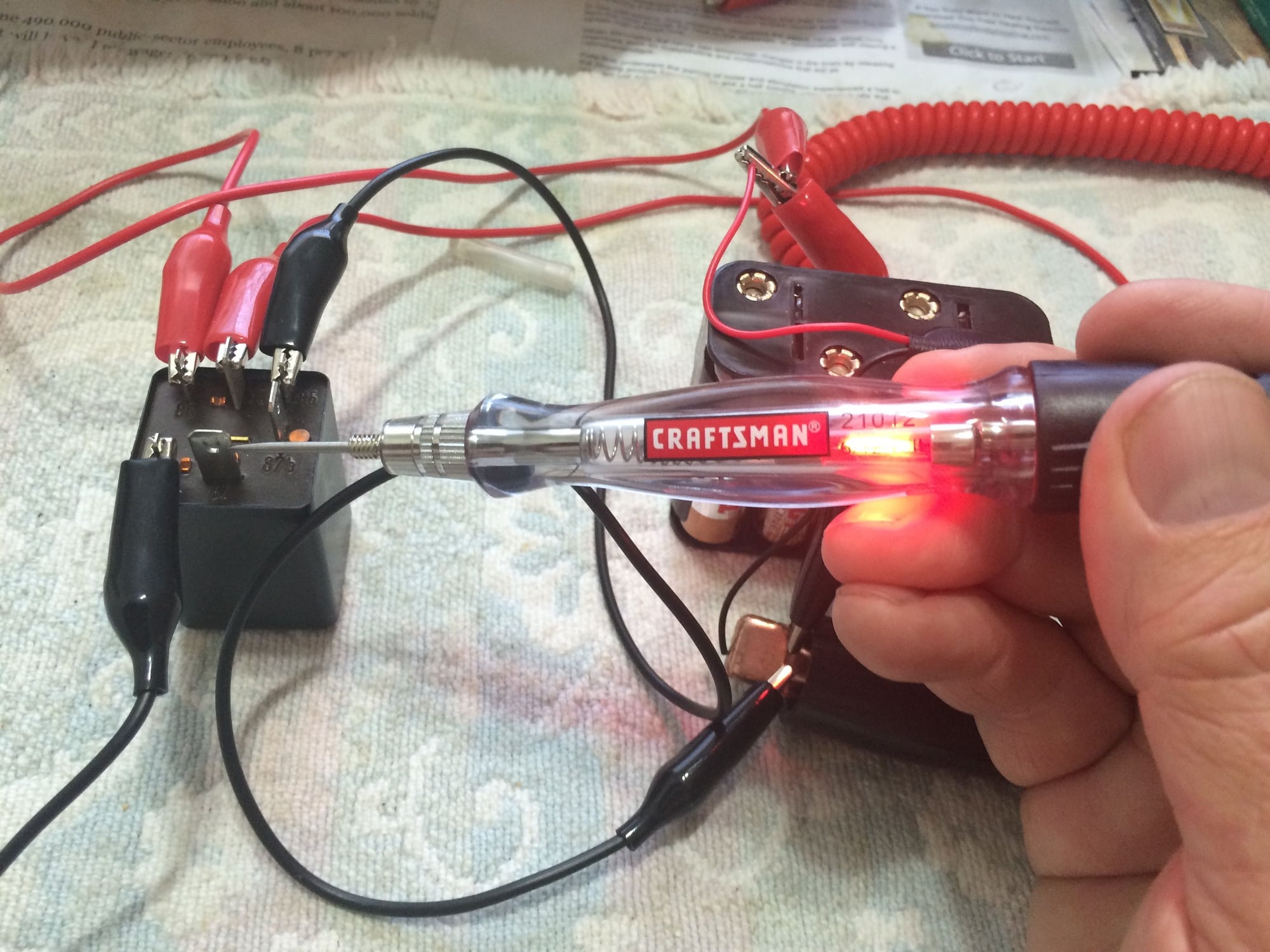
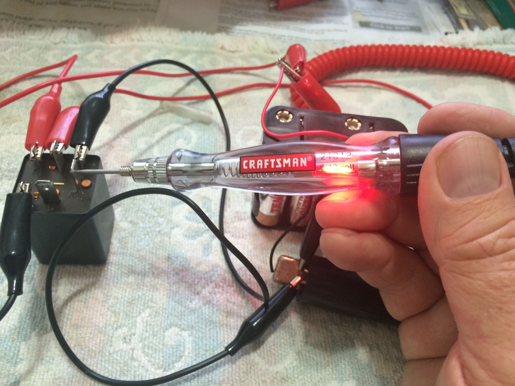
Check that there is continuity between the switch terminals 30 to 87 and
30 to 87b when the coils are energized.
Test setup - coils should click when energized
Checking terminal 30 to 87 continuity
Checking terminal 30 to 87b continuity
Last edited by bruce7; 06-03-2016 at 09:24 PM.
Reason: added more bench testing
The DME determines the precise amount and specific timing of required fuel for
every cycle by collecting information from various DME sensors. The DME sends
an electrical signal of the correct duration and timing to the fuel injector coil.
The injector opens and allows fuel to pass through it into the engine.
The Porsche 993 employs a sequential, multi-point fuel injection system utilizing
a high-impedance fuel injector made by Bosch. The DME manages the fuel
injection system using a voltage controlled driver. A zener diode in the computer
clamps the flyback voltage to control the closing rate of the pintle.
The power side of the injector coil is supplied with 12 volts via the DME relay.
The ground side of the injector coil is connected to a unique pin on the DME.
When the DME has determined the amount of fuel and when to inject it, the DME
activates the injector by switching the normally open ground side injector terminal
to ground.
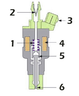
The figure below shows the construction of a typical multi-point fuel injector.
1. Returning spring
2. Fine fuel filter
3. Electrical connector
4. Electrical coil
5. Armature
6. Needle valve (pintle)
According to Bosch the fuel injector has a life expectancy of 1 billion cycles.
In a multi-point injection system there is one injector for each cylinder. The
injectors are located after the throttle and are positioned so that they point at
the back of the intake valves.
Fuel Injector Impedance
The impedance for the injectors used in the 993 is specified in the workshop
manual and by Bosch as 16 ohms.
Fuel Injector Voltage and Current Signals
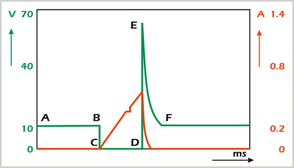
The diagram below shows a simplified view of the voltage and current waveforms.
(The actual current ramp is a �seagull� pattern).
Voltage signal (Green): At point A, the injector is off. At point B, the DME turns
the injector on, by grounding the injector coil, so at point C the voltage drops
to zero. At point D, the DME turns the injector off. At this point there is an
amount of stored energy in the injector coil and a large counter electromagnetic
force (EMF) is generated which causes a large voltage spike at point E. This
voltage spike is also referred to as an inductive kick or flyback voltage. This
voltage is quickly dissipated by the impedance of the injector coil and quickly
returns to 12 volts at point F.
Current signal (Red): At point A, the injector is off. At point B, the DME turns
the injector on, so at point C the current increases through the coil. When the
magnetic field becomes strong enough to overcome the internal spring and fuel
pressure, the needle (pintle) lifts which produces a small dip in the current. The
DME turns the injector off at point E and the current returns to zero at point F.
Testing with the Scope
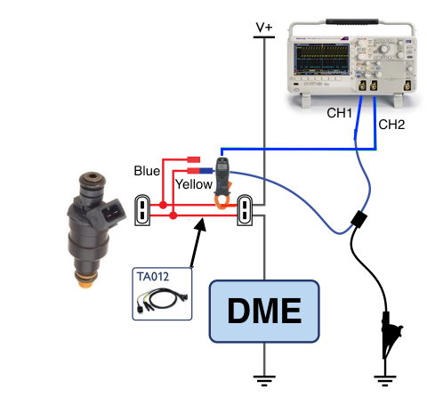
The following diagram illustrates the testing setup.
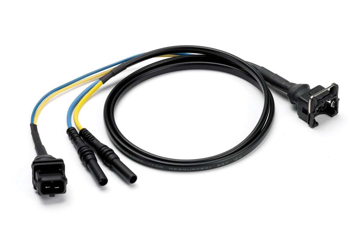
The Pico TA012 test lead is used to connect to the fuel injector.
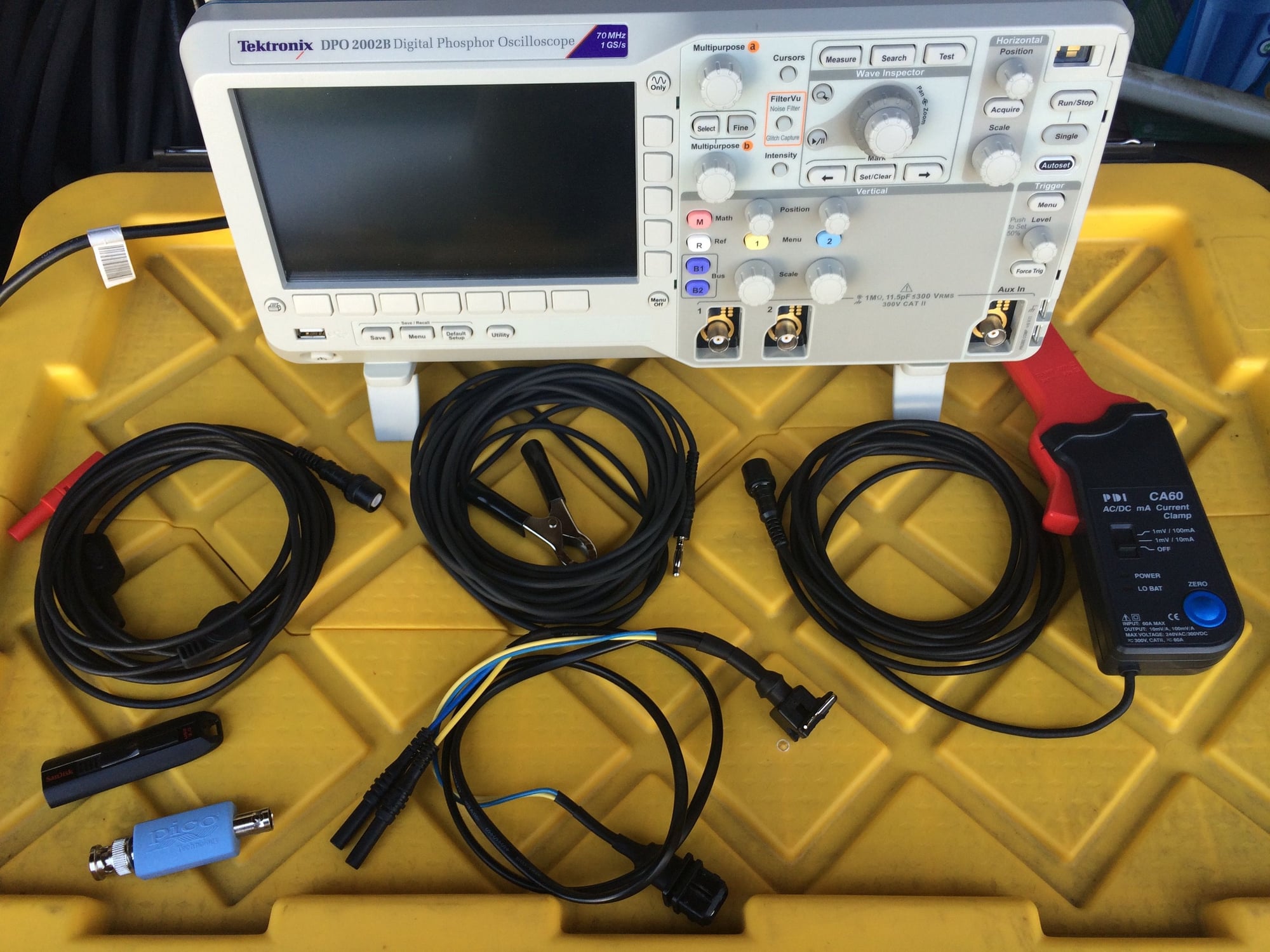
All of the test leads and equipment needed for this test are shown in this photo,
except for the Fluke DMM used to measure injector impedance.
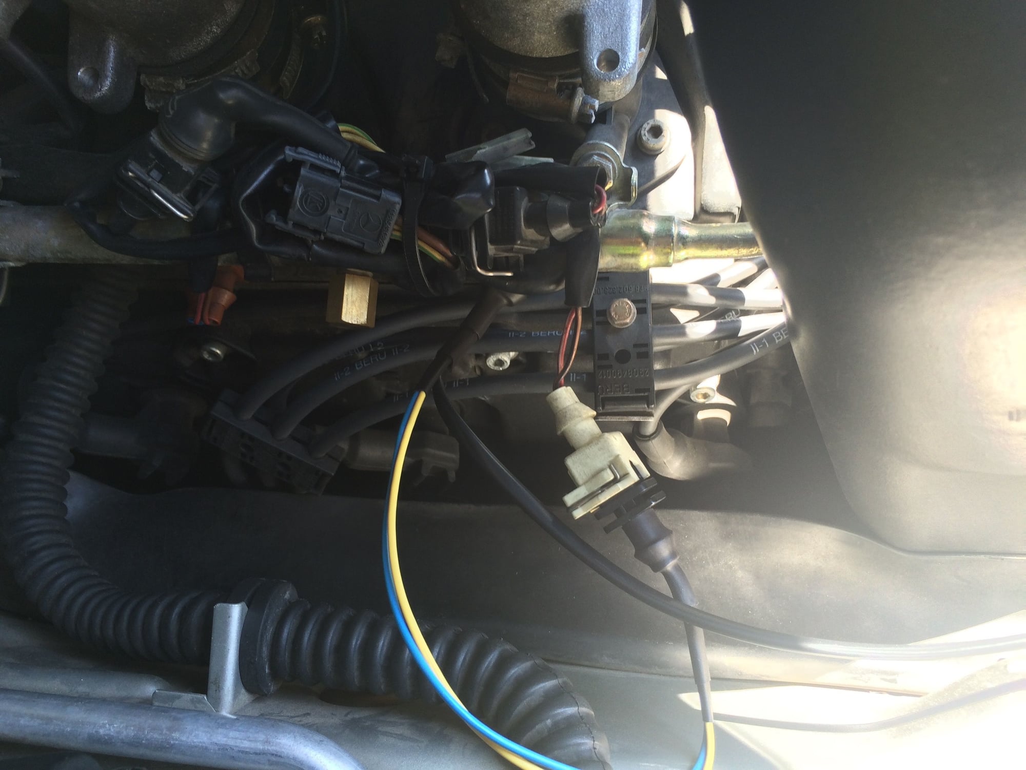
In this photo, looking down at cylinder #1 from the left rear side of the car,
the TA012 has been connected between the injector connector (white connector)
and the injector body (hidden under the fuel rail).
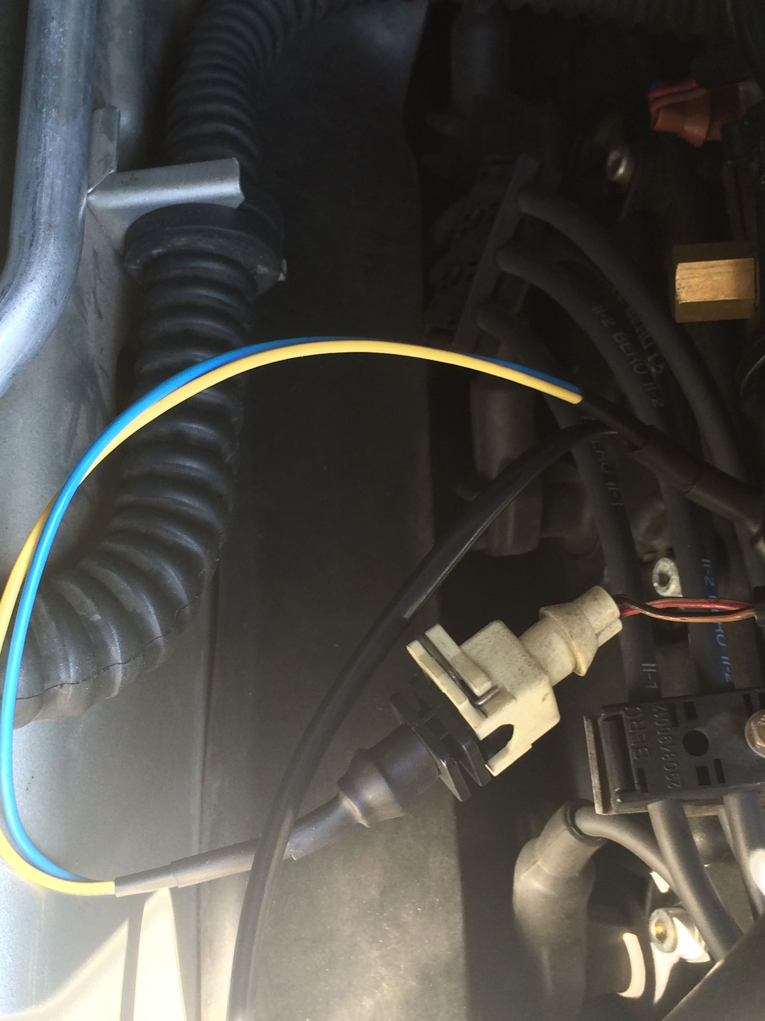
Another view looking forward from the rear of the car where the test leads
have been laid out for easy access.
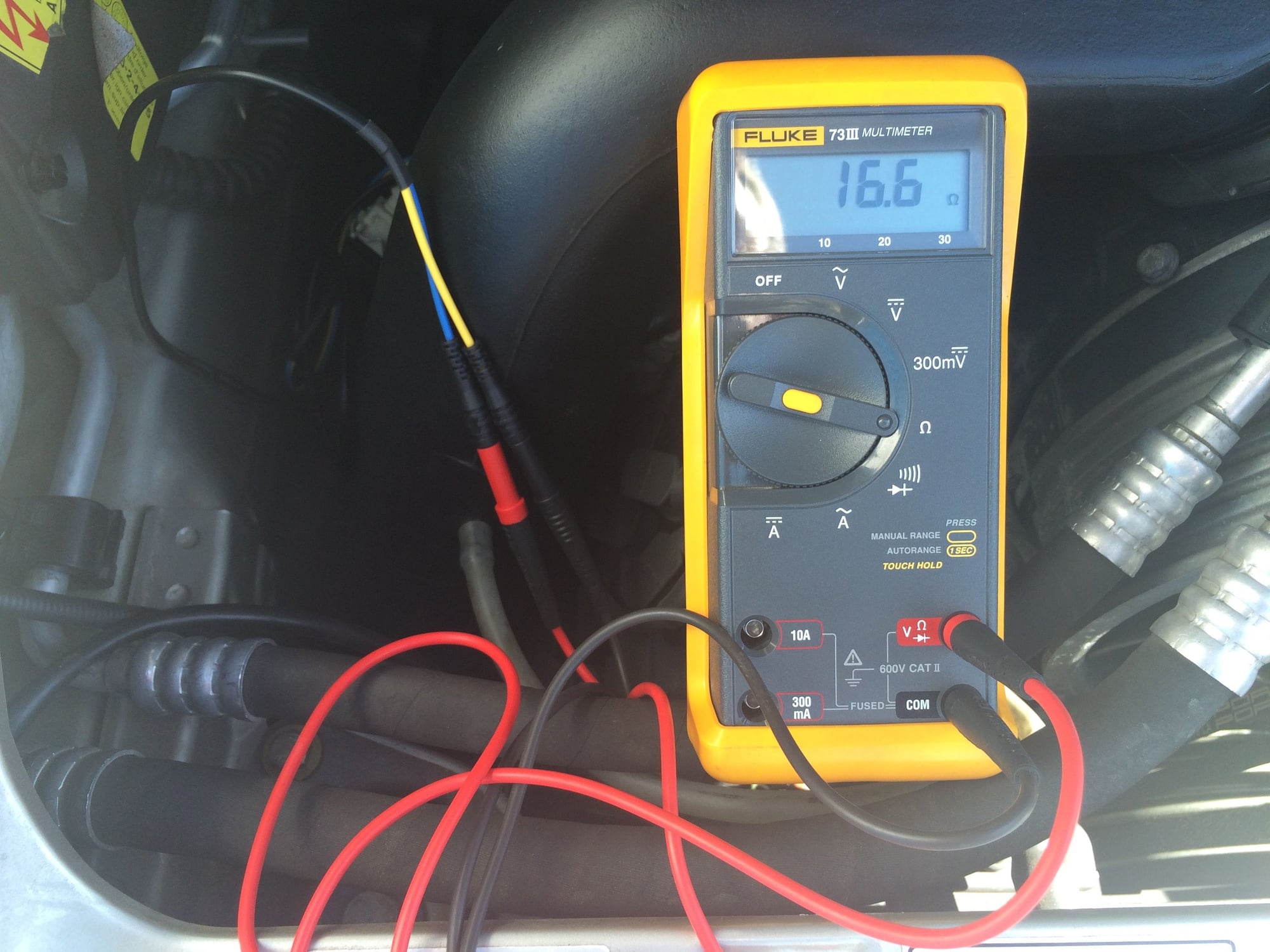
The first test measurement will be checking the injector impedance. For this
injector, the impedance measures 16.6 ohms. The spec is 16 ohms so the
resistance in this injector coil is ok.
The next step is to measure the voltage and current for one injector cycle.
To do so, the scope will be setup so that Channel 1 (Yellow on the scope) will
graph the voltage and Channel 2 (Blue on the scope) will graph the current.
The positive lead of the voltage probe on Channel 1 is connected to the Yellow
lead of the TA012. The negative lead of the voltage probe on Channel 1 is
connected to the battery negative terminal.
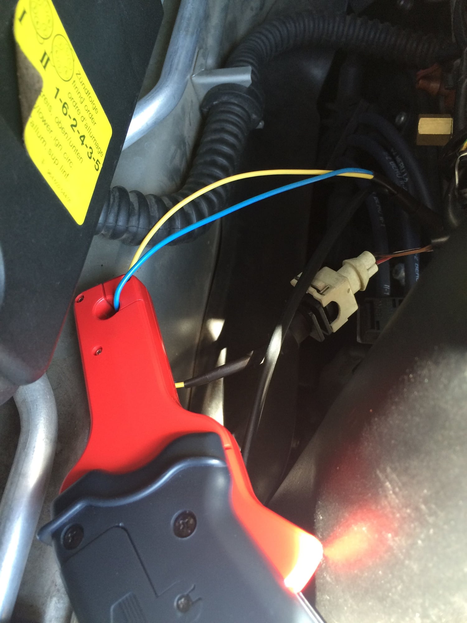
The amp probe connected to Channel 2 on the scope is clamped around the
Blue lead of the TA012. The setting cannot be seen on the amp probe but it
is set to 1mv/10mA.
The scope settings have been set so that on Channel 1, the vertical voltage
scale is set to 5 V per division and on Channel 2 the vertical voltage scale is
set to 50 mV per division. A timebase of 2 ms is used per horizontal division
and a trigger with a falling edge is set with a trigger value of 10.6 V. This will
set the scope to trigger when the DME grounds the injector to turn it on. The
idea is to capture a single waveform for voltage and current that fills the screen
with as much detail and resolution as possible.
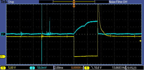
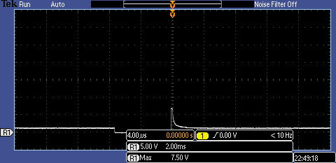
In the image below a capture has been made which shows the voltage and
current waveforms for one injector event.
Test Analysis
Key Voltage Points
Supply Voltage: should be equal to battery voltage
On signal: should be dropped to ground
On time: measured in milliseconds (ms) (about 3.5 ms at idle)
Off signal: inductive kick (about 75 V)
Pintle close: must be steady and consistent. Unsteady movement indicates
sticking or dirty injectors.
In the waveform capture shown above, the fuel injector voltage (yellow trace)
shows the battery voltage at 13.2 V, the on signal (voltage drops to ground) and
the off signal which shows an inductive kick that peaks off screen. (I will make
another capture to get a closer look at the voltage spike below.) The pintle
closes at the off signal on the waveform.
Key Current Points
Current ramp: smooth transition of current rise (ramps upward with no sharp changes).
Pintle bump: opening point of fuel injection pintle shown on waveform with a bump or notch.
Clean off signal: current flow stops with a clean cut off.
Fuel injector current (shown in blue) shows a clean turn on or build up of
current with a steady upward ramp (inductive current reaction of time). Pintle
bump in current waveform shows point of pintle opening. The current waveform
displays the classic seagull pattern.
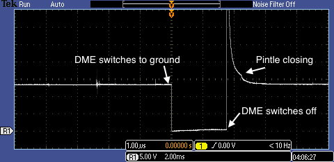
The injector voltage waveform.
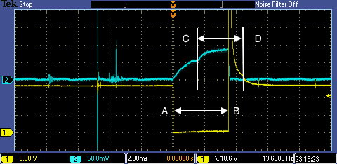
In the ideal case, the injector spray time will equal the commanded
on time by the computer. This can be checked by measuring from points A-B
and from points C-D on the voltage over current waveform. The injector spray
time (from points C-D) is measured from the pintle opening dip to
the pintle closing bump.
However, in practice the injector spray time will be less than the injector
pulse width and will vary by rpm and various factors that make up the
equation the DME uses to calculate the injector pulse width.
Measuring the commanded on time signal (injector pulse width)
of 3.52 ms at idle.
Measuring the actual injector spray time of 2.92 ms at idle.
In the initial capture, the inductive kick peaked offscreen and it�s value could not
be measured as it was clipped by the scope. One of the limitations of the scope
being used is that it cannot zoom vertically very much and even then it loses a
lot of resolution. This is where an automotive scope would be advantageous.
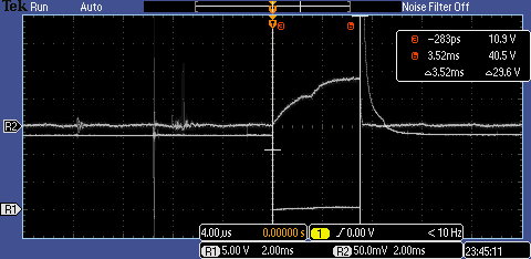
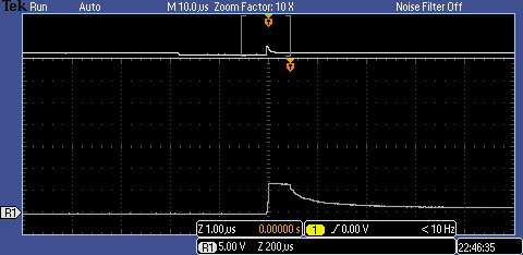
However, there is a way to get that measurement using a 10:1 attenuator on the
test lead as was done in the next capture.
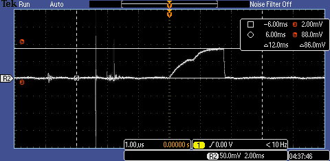
In the new capture below, the inductive kick or flyback voltage can be read as
75 V. The inductive kick is proportional to the number of coil windings and
current flow.
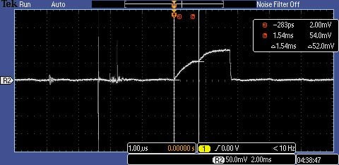
In this image the scope has been zoomed into the voltage peak to reveal a
squared-off top. This indicates the zener diode clamped the voltage spike and
dumped the remainder of the spike. If it is not squared-off that would indicate
the spike was not strong enough to make the zener diode fully dump, meaning
the injector has a weak winding.
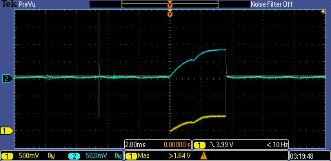
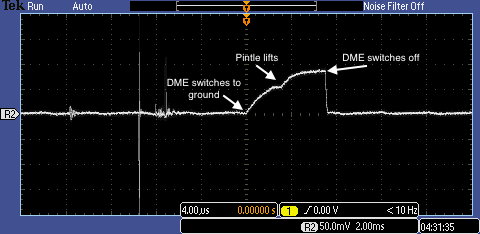
In another new capture, a zoomed in view of the counter voltage is made where
the pintle lifting can be seen in the injector voltage waveform mirroring the current waveform.
The injector current waveform.
In the next capture, the pintle pull-in time is measured to be 1.54 ms. This is
also called the injector turn on time. Factors which affect this are voltage,
current, fuel pressure, pintle spring pressure, and coil resistance. The injector
turn on time should not vary and will remain within 2 ms of the average at all
rpm unless there is an injection system fault.
The total current draw for this injector is measured to be 860 mA.
Analysis for Bad Injectors
I consider the waveforms captured and shown previously to be Known Good
waveforms. If a captured waveform deviates from the Known Good, then a
fault must lie somewhere within the fuel injection system. Analyzing the
waveform can provide direction on where to look for the cause.
Since I don�t have any recorded injector faults of my own, I�m going to hand
draw some examples of bad injector waveforms based upon what I have found
during research.
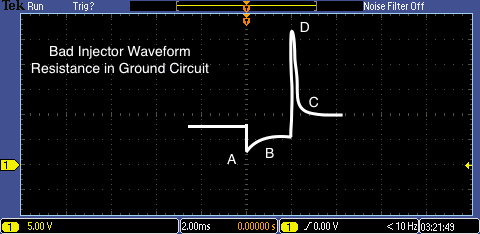
Resistance in Ground Circuit
At point A the voltage drop is elevated from ground (zero Volts)
At point B there is no pintle opening hump
At point C there is no pintle closing hump
At point D the flyback voltage is not low but does not reach 75 V
to engage the zener diode. The flyback voltage may be clipped but not
squared-off.
In this case the injector never opened due to resistance in the ground circuit.
Symptoms include lean misfire and rough running.
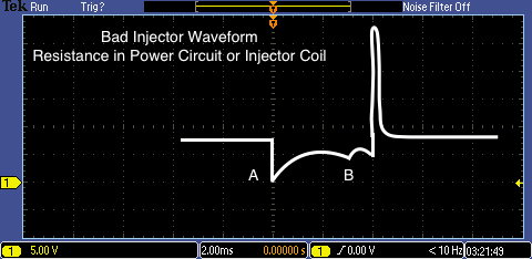
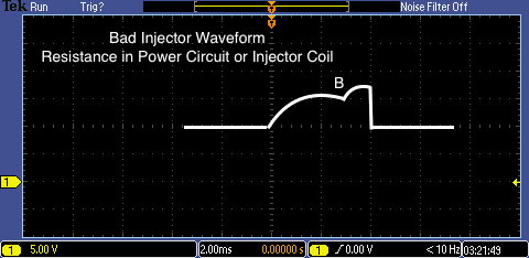
Resistance in Power Circuit or Injector Coil
At point A in the voltage waveform, the voltage initially drops to zero Volts
then rises indicating the resistance is on the power side of the circuit.
At point B the pintle is delayed in opening.
Check injector resistance, it may be > 16 Ohms.
Check DME relay contacts. They may be carbonized, eroded, rusted, or deteriorated.
Check injector connector terminals.
Check DME connector terminals.
Symptoms include lean misfire and rough idle.
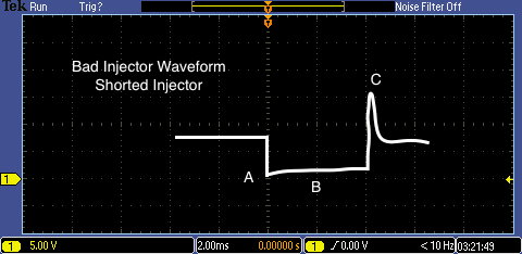
Shorted Injector
At point A the initial voltage drop goes to zero Volts.
At point B the pintle opening hump is very small and the counter voltage rise is nearly flat.
At point C the flyback voltage is very low
Check the injector resistance, it may be less than 16 Ohms.
Symptoms include rough running.
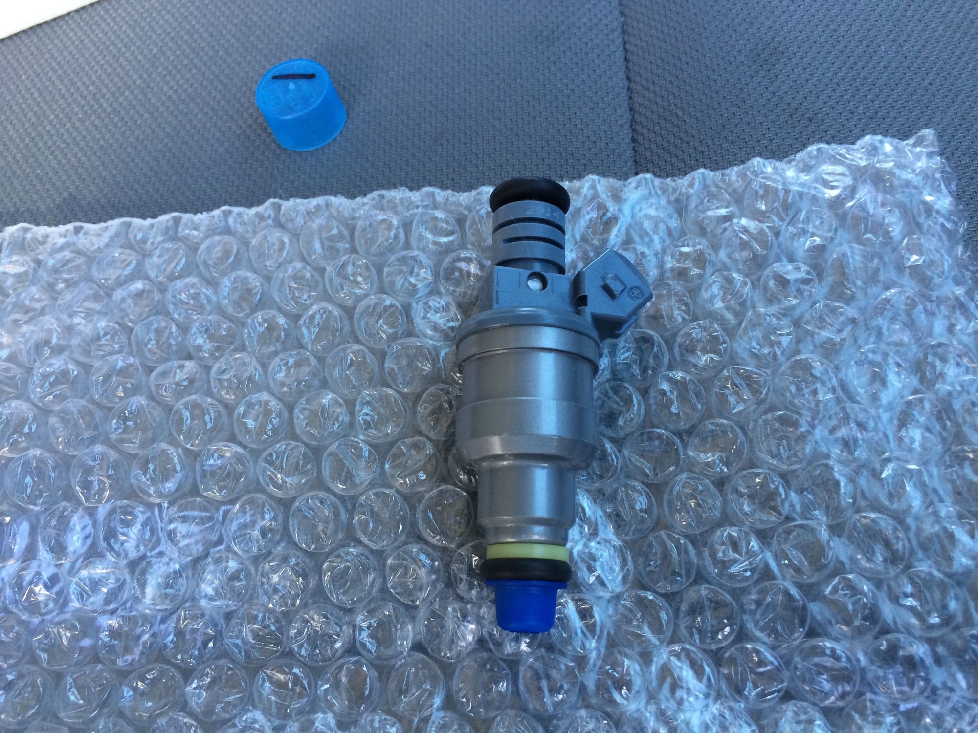
Fuel Injector Maintenance
Periodically, the fuel injectors should be removed and serviced by a shop that
specializes in fuel injectors who can clean, balance and calibrate the injectors.
A 60k miles service interval would be a good plan to keep the injectors in top shape.
Below is a photo of one of the injectors after servicing before refitting.
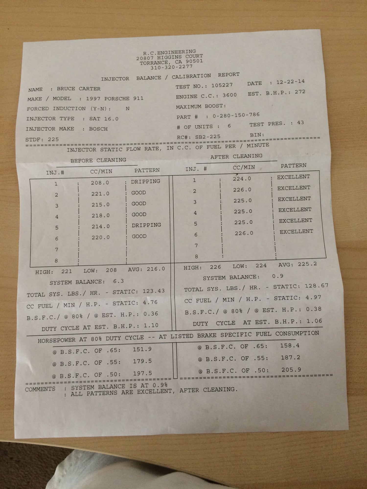
This is the report from the shop as to the condition of the injectors before and
after cleaning. These injectors had about 100k miles on them before cleaning.
Unfortunately I didn�t have a scope at the time when the injectors were
cleaned, so I can�t offer any waveforms that would show the symptoms of a
dripping injector. But I�ll be ready next time to scope them out!
This wraps up my writeup on testing the fuel system.
As I mentioned in the previous post, the injector pulse width and spray time
will vary as it is adjusted by the DME after it has calculated the injector fuel
equation. More on that in a second, but first I want to show some additional
captures done at various rpm to see how the DME adjusts the injector timing.
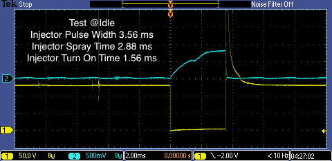
Captures were made at Idle, 2000, 3000 and 4000 rpm. The car was stationary
and was fully hot (oil temperature at 9 o�clock), and the air temperature was
in the mid 90�s.
One other note, during these captures the scope probe factor was left at 10x
rather than setting it to 1x, so voltage readings should be reduced by a factor
of 10. But in this case I�m more interested in the timing than voltage so it can
be ignored.
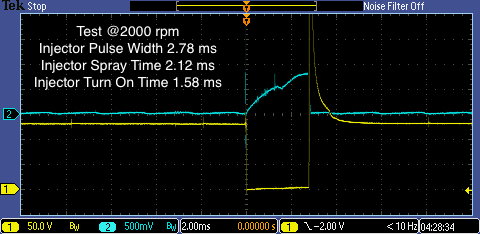
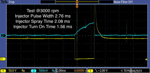
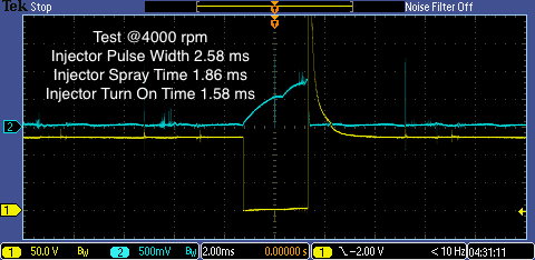
From these graphs it can be seen that the injector pulse width and spray time
get shorter as the rpm increases, yet the injector turn on time remains essentially
constant.
How the injector fuel equation gets calculated is an interesting thing to look at.
Of course, no one except the software engineer that wrote the code for the DME
knows for sure exactly how the fueling equation is calculated. But in general there
are several known factors that are used and there is a very good introduction to
this in the fuel trim part 2 animation on the ATS website:
I've probably missed it in previous posts, but Im going to assume youre an engineer? All your write-ups are great. Thanks for making this post so detailed. Its going to be my end of summer systems check project.
I've probably missed it in previous posts, but Im going to assume youre an engineer? All your write-ups are great. Thanks for making this post so detailed. Its going to be my end of summer systems check project.
Thanks phoneyman! Not working as an engineer now, however, I did
work for many years in the high tech industry as an engineer, mainly on the
software side.
 05-30-2016, 01:31 PM