Normal? - Downstream oxygen sensor heater voltage
 05-28-2013, 05:38 PM
#1
Rennlist Member
Thread Starter
I am measuring unstable voltage on both downstream oxygen sensor heater circuits during the two minutes that the SAI circuit runs after starting a cold engine. 1997 C4S OBDII car.
After the SAI completes, the heater circuit displays battery voltage as I would expect.
The upstream oxygen sensors measure battery voltage during and after SAI operation as I would expect.
I am measuring the voltage between the red/white wire and the brown/yellow wire. The DME controls both downstream heaters through pin 1 of the 88 pin DME connector (https://rennlist.com/forums/993-foru...harness.html#7).
During the SAI operation, I measure battery voltage between the red/white wire and ground.
Normal?
Can someone check this on their car? If you have a cold engine and a multimeter, it should take 10 minutes, including the time to post your results.
Steps:
1. Open engine lid. Find multimeter. Set it to read voltage and set it by the rear of car.
2. Disconnect left side downstream oxygen sensor (gray) on the left hand side of the engine compartment just ahead of the tail light. Push the red interlock, then pull the two gray pieces apart. The black connectors are for the upstream oxygen sensors.
3. Start cold engine.
4. Measure voltage across the two silver female connectors. One of the wires is red/white, the other is brown/yellow. These wires supply battery voltage to the oxygen sensor heater circuit.
5. Does the voltage hop all over the place? Does the voltage stabilize to battery voltage after the SAI completes (after about 2 minutes)?
Last edited by BesideTheBox; 05-29-2013 at 11:56 AM. Reason: fix url
 05-29-2013, 12:49 PM
#2
Rennlist Member
Thread Starter
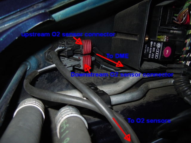
Here are a couple of pictures with labels indicating what's what.
These are the bank1 oxygen sensor connectors in the left rear area of the engine compartment.
I am measuring the unstable voltage on the gray connector that leads to the DME between the red/white wire and the brown/yellow wire while the SAI is operating. After SAI completes, battery voltage is measured between these two wires.
What's what:
Measured wires:
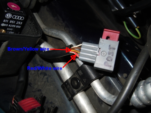
05-29-2013, 03:38 PM
#3
Rennlist Member
Thread Starter
The information below is from the DME Diagnosis section (approximately page 24-18) of the 993 Workshop Manual.
It says that heater voltage is supplied by the DME relay after the engine is started. I assume this means that the potential for 12 volts is always supplied to the oxygen sensor heaters after the car is started. So, possibly, the DME computer just connects pin1 (oxygen sensor heat all downstream) to ground in order to complete the circuit and supply the 12 volts to the sensor heaters. When the heaters are not being run, perhaps pin 1 simply floats, giving the unstable voltage readings that I observe with my multimeter.
Is there an electrical or electronics engineer here that can confirm?
7. Oxygen sensor
The 911 Carrera is fitted with the plunge-proof
oxygen sensor LSH 25. The oxygen sensor is
potential-free and is therefore fitted with a new
4-pin plug connector with separately insulated
wires.
The oxygen sensor is heated by the DME control
unit. Positive supply to the oxygen sensor
occurs across the fuel pump relay inside the
DME relay (as soon as the engine is started).
The ground connection is made via the DME
control unit. If the engine has already reached
the operating temperature and is then driven
at heavy loads and high engine speed, no
additional heating of the oxygen sensor is
required. In this operating state, the DME
therefore cuts off the supplementary sensor
heating.
The oxygen sensor is monitored by the DME
control unit. The sensor voltage may additionally
be read off using the System Tester and the
"Actual values" menu item. If problems occur
at the oxygen sensor, start troubleshooting by
checking operation of the sensor heater. A voltage
of approx. 12 V should be present at the
sensor plug when the engine is at idle.
05-31-2013, 12:34 PM
#4
Rennlist Member
Thread Starter
Bringing this thread to a close.
I received off-list confirmation that the downstream oxygen sensor heaters are not run while the SAI is running after a cold engine start.
The unstable voltage readings that I read are a result of system design. Pin 1 at the DME connector (connected to the brown/yellow wire at the connector pictured above) is left to float until the heater is switched on.
The DME switches on the downstream heaters by grounding pin 1, completing the 12 volt circuit to supply heat to these oxygen sensors.