

1995 OBD1 Diag tool
 08-17-2006, 01:56 PM
#136
You have many incorrect data displayed which basically makes your scanner/tester
limited in utility:
1. The 964 doesn't have a MAF nor a MAP sensor.
2. The ignition timing is NOT .8 degrees at idle.
3. Most likely you don't have a FQS (fuel quality switch).
If so, it should be set so the value is zero.
4. The O2 sensor value is incorrect. It should be close to .50 volts.
Discorrect it and measure it with a voltmeter with the engine running.
5. NTC I is the intake air which is incorrect and should be less than
the NTC II (head temp).
6. Channel 5 appears to a be an unconverted Hex value ($FD), i.e. decimal 253.
That's a start.
The most useful function for a 964/993 scanner is the access to the ABS, SRS, & CCU
ECUs and NOT the engine DME ECM. You should be able, i.e. if it works properly, to:
1. access the faults codes
2. reset the faults codes
3. test and measure their inputs, e.g. CCU sensors, & etcs
4. and most importantly drive the outputs, e.g. CCU fans & vents
based on **** & button settings.
The above provide the real value of the PST2 versus aftermarket units which just
read faults (sometimes incorrectly) & reset them and some inputs.
Last edited by Lorenfb; 08-17-2006 at 11:18 PM.
 08-17-2006, 06:21 PM
#137
Instructor
Thread Starter
Join Date: Dec 2005
Posts: 132
Likes: 0
Received 0 Likes
on
0 Posts
Julian,
I assume some of the pics are for a 993, then for the 993:
I have a much updated version of scantool.txt in the #1 message of this thread. Use scantool4 to get all the features including TEST OUTPUTS. Then replace the pics in your message #135 or replace message.
Lambda and Adaption don't work yet. Doug is looking at the code. These point to the wrong (964) memory locations. I don't believe 993 has Adaption function. If you read through all threads you'll find these discussed.
Idle RPM is ~900 cold and 800 warm. I put many limits in the scantool.txt Not necessarily correct but best I could figure out.
Thanks,
Ray
Last edited by raycm; 08-17-2006 at 08:23 PM.
08-17-2006, 08:36 PM
#138
Originally Posted by raycm
Julian,
I assume some of the pics are for a 993, then for the 993:
I have a much updated version of scantool.txt in the #1 message of this thread. Use scantool4 to get all the features including TEST OUTPUTS. Then replace the pics in your message #135 or replace message.
Lambda and Adaption don't work yet. Doug is looking at the code. These point to the wrong (964) memory locations. I don't believe 993 has Adaption function. If you read through all threads you'll find these discussed.
Idle RPM is ~900 cold and 800 warm. I put many limits in the scantool.txt Not necessarily correct but best I could figure out.
Thanks,
Ray
I assume some of the pics are for a 993, then for the 993:
I have a much updated version of scantool.txt in the #1 message of this thread. Use scantool4 to get all the features including TEST OUTPUTS. Then replace the pics in your message #135 or replace message.
Lambda and Adaption don't work yet. Doug is looking at the code. These point to the wrong (964) memory locations. I don't believe 993 has Adaption function. If you read through all threads you'll find these discussed.
Idle RPM is ~900 cold and 800 warm. I put many limits in the scantool.txt Not necessarily correct but best I could figure out.
Thanks,
Ray
My screens show results for my 964 (sorry to be polluting the 993 board!) ... I'm unclear whether the config file that comes as part of the ScanTool4 download is for a 964, or a 993, or how to configure the range settings in it.
I suppose we are at the "bleeding edge" of the technology here, so maybe I should wait a while until more folks have tried the boards and software.
 08-18-2006, 01:20 AM
#139
Technical Guru
Rennlist Member
Rennlist Member
Originally Posted by Lorenfb
1. The 964 doesn't have a MAF nor a MAP sensor.
Originally Posted by Lorenfb
4. The O2 sensor value is incorrect. It should be close to .50 volts.
5. NTC I is the intake air which is incorrect and should be less than the NTC II (head temp).
5. NTC I is the intake air which is incorrect and should be less than the NTC II (head temp).
I'm not 100% on the absolute voltage levels but relative to each other the values are correct (and already complimented).
Originally Posted by Lorenfb
6. Channel 5 appears to a be an unconverted Hex value ($FD), i.e. decimal 253.
Originally Posted by jjbunn
I'm unclear whether the config file that comes as part of the ScanTool4 download is for a 964, or a 993,
08-18-2006, 01:48 AM
#140
"While technically not a MAP sensor doesn't the altitude "switch" (ADC BC07) measure pressure?"
Right, it's NOT a MAP nor a switch. It's an altitude sensor and should be indicated
as such, e.g. be displayed (like typical OBDII scanners) as 29.9" Hg as nominal.
"The input channels are the raw, uncorrected output from the ADCs"
Right, so what's the value of displaying them to user in that form?
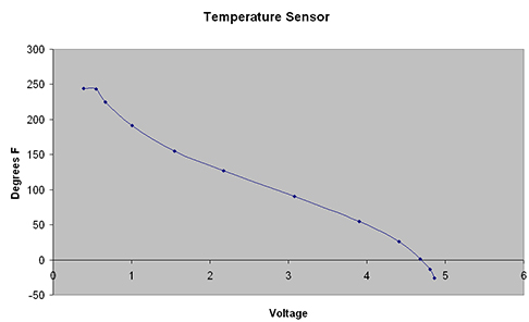
So what are the units of NTC I & NTC II? Are they in units of resistance
(or raw decimal data)? Then they would be correct or should they be converted to
something useful like degrees C or F. Maybe measure each using an ohmmter
and then develop an equation to indicate each as a resistance for INPUT values
and as a temp value for ACTUAL values (as is the case now).
"Channel 5 is the Country Code (Term 39)."
So, indicate it as such.
Bottom line: It you're making a useful scanner, provide proper data!
Also, there needs to be a "branch"/selector in the software between 964/993.
Remember, who will be the majority of the users of this device and their abilities.
The real/main purpose of this device should be as an aid to troubleshooting.
If the data it provides have no utility for this, then the data have questionable value.
Right, it's NOT a MAP nor a switch. It's an altitude sensor and should be indicated
as such, e.g. be displayed (like typical OBDII scanners) as 29.9" Hg as nominal.
"The input channels are the raw, uncorrected output from the ADCs"
Right, so what's the value of displaying them to user in that form?
So what are the units of NTC I & NTC II? Are they in units of resistance
(or raw decimal data)? Then they would be correct or should they be converted to
something useful like degrees C or F. Maybe measure each using an ohmmter
and then develop an equation to indicate each as a resistance for INPUT values
and as a temp value for ACTUAL values (as is the case now).
"Channel 5 is the Country Code (Term 39)."
So, indicate it as such.
Bottom line: It you're making a useful scanner, provide proper data!
Also, there needs to be a "branch"/selector in the software between 964/993.
Remember, who will be the majority of the users of this device and their abilities.
The real/main purpose of this device should be as an aid to troubleshooting.
If the data it provides have no utility for this, then the data have questionable value.
Last edited by Lorenfb; 08-19-2006 at 01:30 AM.
08-18-2006, 10:54 AM
#141
Advanced

Join Date: Jun 2001
Location: Florida
Posts: 99
Likes: 0
Received 0 Likes
on
0 Posts
Just a note:
The version of the scantool software that's out there now will not work with just any car out of the box. You have to obtain a proper version of scantool.cfg for your car. The scantool.cfg that is included was setup for my car and my car only.
If any listers have a special version of the scantool configuration I would be happy to include it in the software package and perhaps I could enhance the software to work with multiple vehicles.
-doug
08-18-2006, 12:18 PM
#142
Rennlist Member
Originally Posted by JasonAndreas
... So for instance the NTC sensors need to have their output logically complimented and then passed through a lookup table to linearize the values. Someone was looking for the data:..
08-18-2006, 02:47 PM
#143
Racer
Join Date: Nov 2003
Posts: 424
Likes: 0
Received 0 Likes
on
0 Posts
Ray has designed some circuit updates, which are incorporated into the schematic and PCB layout below:
- LEDs as connection and transmission indicators on the board (Power, K Data, L Poll)
- +/-V on the RS232 receive for those who need it.
The updated BOM is available in Post #134
Other fixes include:
-Transistors and diodes in a consistent orientation
-Switch terminals layed out to match board-mounted switch terminals better
-More markings on the board (such as resistor and transistor values, switch functions) to ease assembly.
Unless anyone spots errors in my layout, this is hopefully the final rev. of the board. If there are buyers, we can either go the $26 route I outlined above (very expensive for what it is, but it's a known quantity), or someone else can take on the task of shopping around and getting a cheaper board. I am happy to provide hi-res bitmaps and artwork files if someone wants to step up.
Colin
08-18-2006, 02:55 PM
#144

Doug,
I wouldn't sweat too much, as a free tool its extremely good value for money. Yes it might need some edges rounding off which I think are just fine tuning and bug fixing within the community but where can you get anything that comes close to what you've done for OBD1. All the variations have come from the community experimenting rather than a set of requirements at the start.
Hats off to you and the experimentors amongst us.
Here's one happy experimentor.
BR, Mark.
08-19-2006, 01:53 AM
#145
Originally Posted by JasonAndreas
"Originally Posted by jjbunn: I'm unclear whether the config file that comes as part of the ScanTool4 download is for a 964, or a 993,"
One (not-so-easy) way to tell is to look at the Engine Speed RPM actual value
address, the 964 uses 0x3A and the 993 uses 0x39.
Many thanks ... I guess my next question is: how do you know that? Is there a document you are referring to that lists the addresses of the various registers? How would I get hold of that reference material?
08-19-2006, 05:06 PM
#146
Instructor
Thread Starter
Join Date: Dec 2005
Posts: 132
Likes: 0
Received 0 Likes
on
0 Posts
Originally Posted by jjbunn
Hi Jason ...
Many thanks ... I guess my next question is: how do you know that? Is there a document you are referring to that lists the addresses of the various registers? How would I get hold of that reference material?
Many thanks ... I guess my next question is: how do you know that? Is there a document you are referring to that lists the addresses of the various registers? How would I get hold of that reference material?
If your talking to your DME you have the correct scantool.cfg. Basically all the scantool.zip files so far produced come with the 964 files only.
The scantool.cfg file can be viewed/modified with NOTEPAD.
Ray
08-21-2006, 12:28 PM
#149
Three Wheelin'
Im definitely in for a PCB board. COWTOWN - do you have a paypal account? $26? Woo Hoo!
I also suggest that we start a new thread titled "GB: OBD1 PCB board" or something like that. Since this thread is soooooo long, there may be others interested in the board but have not been following this thread.
I also suggest that we start a new thread titled "GB: OBD1 PCB board" or something like that. Since this thread is soooooo long, there may be others interested in the board but have not been following this thread.
08-21-2006, 12:49 PM
#150
Rennlist Member
Originally Posted by tj90
...I also suggest that we start a new thread titled "GB: OBD1 PCB board" or something like that. Since this thread is soooooo long, there may be others interested in the board but have not been following this thread.