When you click on links to various merchants on this site and make a purchase, this can result in this site earning a commission. Affiliate programs and affiliations include, but are not limited to, the eBay Partner Network.
C'mon, Rennlist, you're supposed to be the smart ones...don't let me down (everyone else has...)
1992 968, just got it and the speedometer (and, of course, odometer) is inop. Cruise doesn't work either, but I'm sure that's related to the speedo (wiring diagram shows cruise signal is an output from the speedo).
To date:
- No ABS warning lights
- Used a VOM at the sensor to verify that I am getting an AC signal from the left front ABS sensor
- Cannot really tell if the ABS pump is "priming" as I was told to look for; MAYBE I head a faint "grunch" from the right front when I'm backing up? It's not very obvious and I'm not feeling anything in my butt, steering, or pedals
- Sorta-kinda tested the ABS on a mostly-dry road and maybe felt the ABS kick in, but there's not really a good/safe place to test full-on ABS in Connecticut
- Tested with a different frequency converter (used); no difference
- Tested with a different cluster (used); no difference
- Cleaned off all the cluster terminal connectors, no difference.
So I cracked open the wallet and bought a Durametric. Kinda disappointed at the low functionality available in this spendy thing, compared to the Ross Tech for my VW, but given it's a '92 I shouldn't be surprised at all. Anyway:
- No ECU fault codes
- And...no speed indicated by the ECU when driving
So, I'm at an impasse. Possibilites are that the left front ABS sensor is actually bad -- but wouldn't that lodge an ABS system fault code? And unless the used parts I tried also failed...what now? I'm stumped as to what to check next.
I'm happy to ring out any wiring anyone suggests, but be specific; the PDF wiring diagrams that are online are crap and annoying.
Any ideas appreciated...or if someone is looking for a mechanically-good driver-quality 968... - GA
I'm trying to connect with a 968 owner nearby to see if I can hook up my oscilloscope and determine what inputs to the FCU make the speedo work. Don't give up hope just yet.
have you checked the speed sensor to verify that it is operational? It sends signal to the DME, which then sends to the speedo. Speedo signal comes out of DME on pin 9. If I read things correctly, input signals from speed sensor are on pins 48&49.
have you checked the speed sensor to verify that it is operational?
"Speed sensor"? Every source I have found so far indicates that the speedo (thus cruise) speed signal for the 6-speed 968 comes from the left front ABS sensor.
Where is this speed sensor? What is its part number? It does not come up in the "KATALOG" or a parts search. Searching for "speed sensor" in most common Porsche parts sources only comes up with ABS sensors and crankshaft position sensor.
have you checked the speed sensor to verify that it is operational? It sends signal to the DME, which then sends to the speedo. Speedo signal comes out of DME on pin 9. If I read things correctly, input signals from speed sensor are on pins 48&49.
The speed sensor in the wiring diagram (going to pins 48 and 49) is the flywheel speed sensor, which has nothing to do with the speedometer.
Well, this is precious...since I had already tested the left front sensor for a signal (it's good) and there's no ABS fault codes (good) i figured the next thing I'd check is if the signal is getting to the ABS computer. And then maybe I could figure out if teh speedo signal was coming out of it to the speedo (though I've yet to nail down what that wire is).
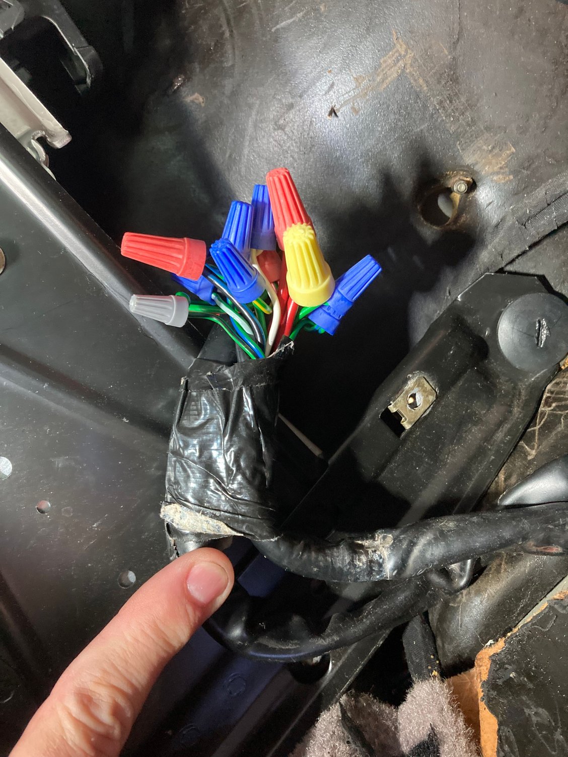
As I pulled back the passenger floorboard stuff to find the ABS computer (I've been in there a couple times to R&R the ECU), I looked to the right and found the item below.
Anyone have ANY clue what this could be all about? What are those two harnesses and why did someone graft them together? And for the love of Ferdinand, why did they use acorn nuts???
I did find what I think is the ABS computer, 0 265 103 039, mounted on the right side behind the diagnostic port. But I'm not going to dig into that until I figure out - and repair - what is going on here.
This is definitely some "DAPO" action...anyone want a 968 with fresh service and replaced balance and t-belts? Sigh...
Man, I sure hope so...but I'm not convinced. It goes from the firewall then what appears to be a panel down the right side, possible toward the door frame (everything there is working?) I can't see any relation to the ABS computer.
But it's decisively "wrong" and I'm going to spend some time soldering these wires together and heat-shrinking them to ensure that's not the problem.
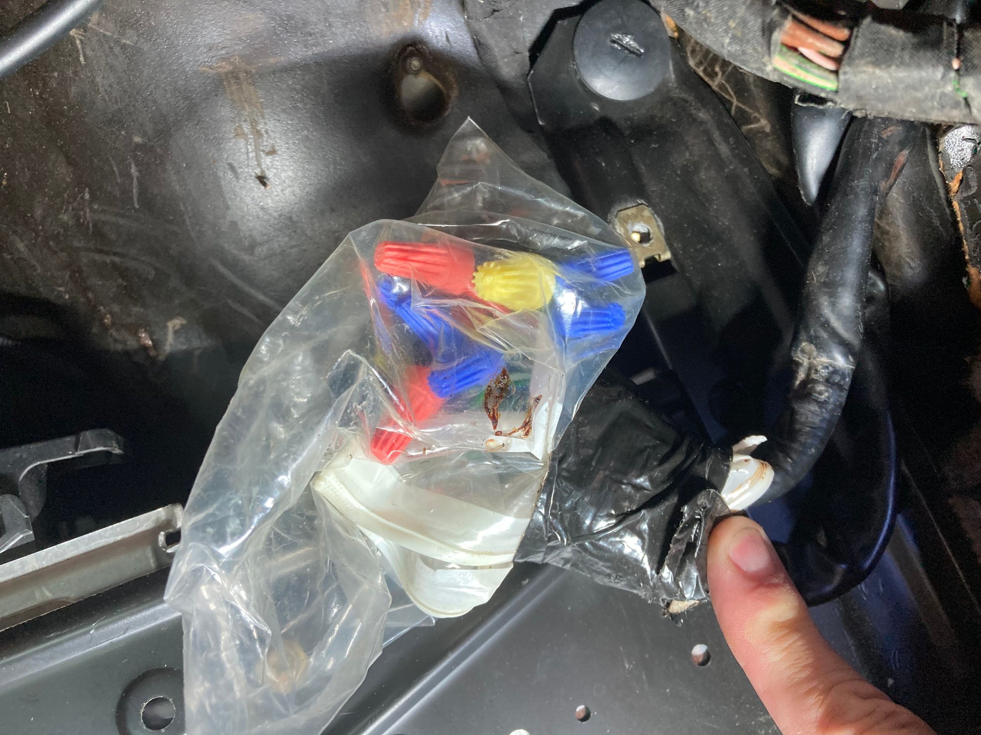
Can anyone determine what these are for? My buest guess is a mouse got to 'em, but there's no other mouse evidence, like eaten up insulation.
I expect to be back ina few hours with the news that they're all tidied up, and my speedo still doens't work. So don't give up thinking about this yet.
Man, I sure hope so...but I'm not convinced. It goes from the firewall then what appears to be a panel down the right side, possible toward the door frame (everything there is working?) I can't see any relation to the ABS computer.
But it's decisively "wrong" and I'm going to spend some time soldering these wires together and heat-shrinking them to ensure that's not the problem.
Can anyone determine what these are for? My buest guess is a mouse got to 'em, but there's no other mouse evidence, like eaten up insulation.
I expect to be back ina few hours with the news that they're all tidied up, and my speedo still doens't work. So don't give up thinking about this yet.
So frustrating.
Looking at some of the colors in the bundle, I would say that they are the main harness to the ABS computer. At least thats what the wiring diagram shows.
Looks like someone cut the harness, then tried to reconnect it in the worst possible way.
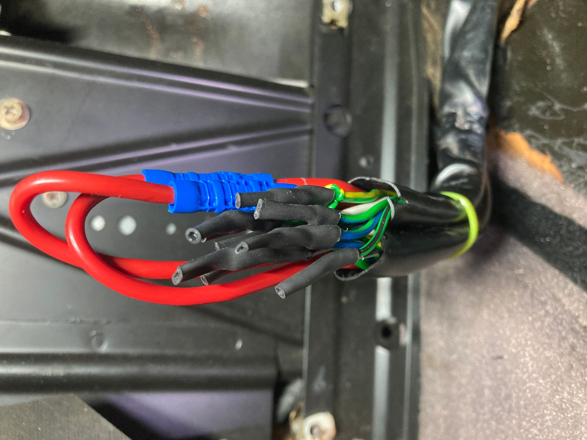
Wires repaired...not awesome, but functional. Didn't fix the speedo prob; I wasn't confident that it would, given it looks like the wires are heading for the right door. But at least I know now that these wires were decisively NOT the problem.
I'm putting off testing the LF ABS signal to the control unit for tomorrow, as there's beer pending for me tonight.
I made a post while I was in the garage with the colors but I guess I didn't hit "Submit"...your basic two big ~12G red wires, one white, one green, the others variations of Green/something Blue/Something. Headed straight for the bellows that went into the door so I'm thinking it was something there. Mirror over there works, window works, locks don't work but they never have either side (I can hear the solenoids trying...low priority fix, I can reach over and hit the ****).
I'm suspecting it was a poor mouse damage repair, or someone installed doors on this car that had features it didn't originally come with (power mirrors/doors).
The harness from the ABS control unit connects to the ABS hydraulic unit that is under the passenger (right side) fender. You will have to remove the fender liner to see the unit. It is mounted to a metal perch. Doesn't go to the door.
The harness from the ABS control unit connects to the ABS hydraulic unit...
(I can't hate those wiring diagrams more than I do right now...)
I'm not so worried about the hydraulic system; I'm reasonably confident that the ABS system itself is working fine.* So what I'm looking for now is from where on the ABS control unit the "speed out" wiring goes, and to where (I presume it goes to the frequency converter, and then to the instrument cluster). I can't imagine that this wiring goes all the way out to the hydraulic unit and then back into the dash panel...? Then again, it's a '90s German car, so...
My best clue from my fav wiring diagrams** is that it may be pin 17 on the ABS CU. That is a 0.5mm PK/BK wire which goes to the T40 connector in the passenger compartment, then to pin 6 on a device labeled "FCU", which I interpet as Frequency Converter Unit (though, for whatever reason, it's got "ONLY SAUDI ARABIA" below it...) The output from there seems to be a BK/RE 0.5mm wire to pin B14 instrument cluster plug, going to "E-TACHO" which maybe I'm mis-interpreting as the tachometer (USA parlance), however that's the German word for "speedometer" so I'm thinking that's it.
So my plan right now, if/when I get motivated (and Sunday of Memorial Day weekend is not that day) is to verify that the LF ABS sensor signal is getting to pins 4 and 6 on the ABS CU terminal plug, then seeing if that same signal (I hope it's the same signal) is getting to pin 6 on the FCU (and that the FCU is getting properly powered up). From tehre we ring out the wire from the FCU to the B14 pin behind the cluster, and then from there to...somewhere.
Who said you don't have to be a detective to work on cars...? - GA
* I think I'm hearing a faint "grunch" in the right front corner when I start moving, there's no ABS warning light, and I tested the ABS system on a slightly-damp road a couple weeks ago and it seemed to work.
** I just found a paper copy on eBay, with binder. I'm just going to crack open the wallet and buy it.
Sorry for my earlier post, I was kind of tired and not looking at things correctly. The FCU is relay G16, and takes the pulse signal and converts it to analog voltage for the speedo. Not sure about how things are labeled, but I was wondering if the TDM/TOM? is the speedo in the cluster.
 05-24-2024, 06:19 PM