When you click on links to various merchants on this site and make a purchase, this can result in this site earning a commission. Affiliate programs and affiliations include, but are not limited to, the eBay Partner Network.
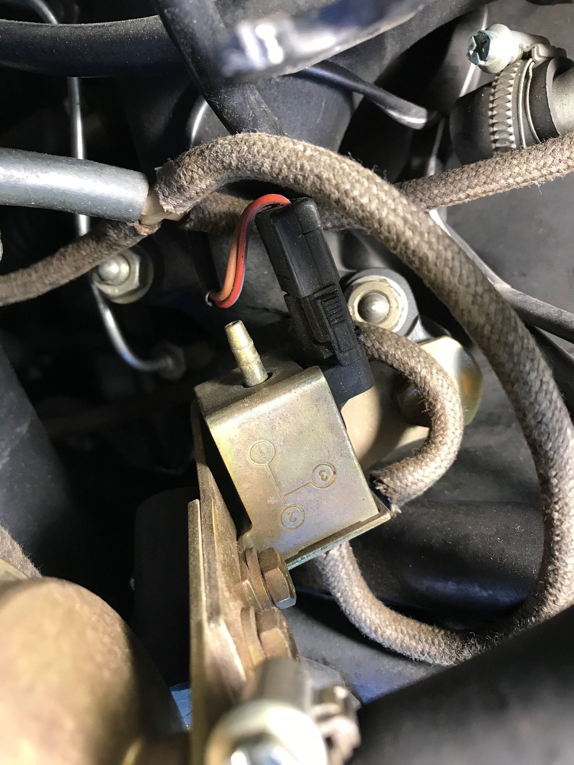
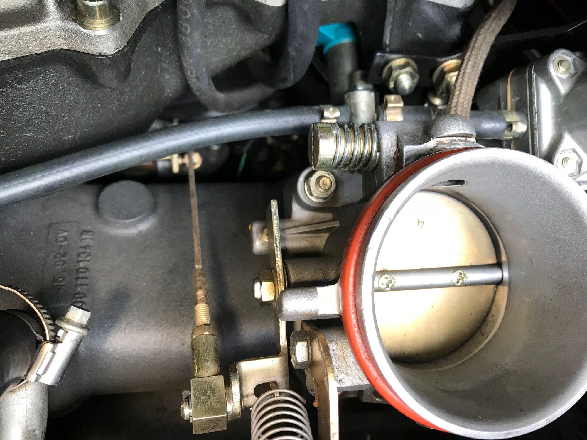
Missing hose coming off position 1 here - anyone know where it should go? Unable to find one fallen off or another connection point...
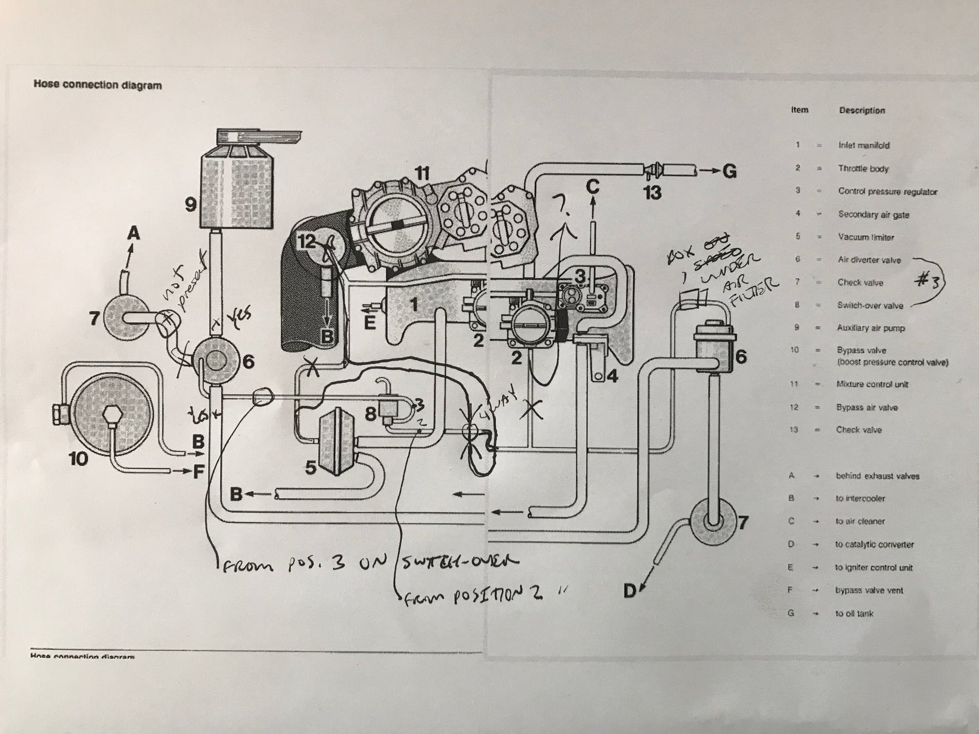
Seems to be on this diagram, not totally clear. Doesn't show where it should go, or which one it is (the 1,2,3 positions):
On the pic you have of your car, I see 4 vacuum hoses connected together, there should be only 3, one of the should be connected to the change over valve.
On the pic you have of your car, I see 4 vacuum hoses connected together, there should be only 3, one of the should be connected to the change over valve.
The diagram seems to indicate that 3-way joint piece further forward in the engine, which I do have and has a line going to that. The 4-way joint you speak of near the switch as you point out, also has a line from the switch going to it. Which leads me to believe this diagram is not for an M64.50 vacuum system, perhaps the regular 964 or turbo 3.3. Hmmm.
OR: since another car has been confirmed same as mine (Position 1 to atmosphere), maybe there was a modification people did to the hose routings to accommodate a disconnected smog pump?
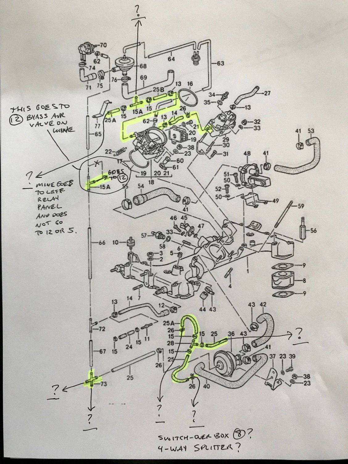
There are numerous differences between my system and this diagram. Some highlighted are:
- There is no large hose connecting 6 and 7. 6 (on the left 6) has the other three lines present and no port for anything to 7 available.
- 5's vac hose goes to the 4-way splitter pictured earlier, not to 12.
- 12's vac hose goes to the 4-way splitter (by way of a tee or two along the way), not to 5. It also does not connect (as in the diagram) to the larger hose going across from left of engine bay seemingly from the electric panel across the engine to 2 and 3.
- 2's vac line reverses and goes behind the air box somewhere, not tied into line between 8 and 6.
- line from 8 to 6 arrives at 6, but by way of the 4-way splitter and then small box mounted under air filter.
Is it amazing the car even runs? Or is this diagram for an ROW emissions setup or something?
[QUOTE=wicks;15061225]There are numerous differences between my system and this diagram. Some highlighted are:
- There is no large hose connecting 6 and 7. 6 (on the left 6) has the other three lines present and no port for anything to 7 available.
- 5's vac hose goes to the 4-way splitter pictured earlier, not to 12.
- 12's vac hose goes to the 4-way splitter (by way of a tee or two along the way), not to 5. It also does not connect (as in the diagram) to the larger hose going across from left of engine bay seemingly from the electric panel across the engine to 2 and 3.
- 2's vac line reverses and goes behind the air box somewhere, not tied into line between 8 and 6.
- line from 8 to 6 arrives at 6, but by way of the 4-way splitter and then small box mounted under air filter.
Is it amazing the car even runs? Or is this diagram for an ROW emissions setup or something?
Someone has your hoses all messed up, just connect the hoses the way it shows in the diagram you posted exactly the way may 965 is also. call me if you have any concerns and try to help.
In order to do that I would need different splitter parts. Specifically with 12 to 5 to 2, those hoses are of very different size/material. In order to connect 12 into the hose from the relay panel across the motor to 2 and 3, I would need to cut that hose and add a multi-sized T. That hose looks very original and is of a special material that makes me very much not want to cut it. I'm thinking this connection setup may work, but it may not be literal meaning the cars may not have actually been built the way this diagram shows the system.
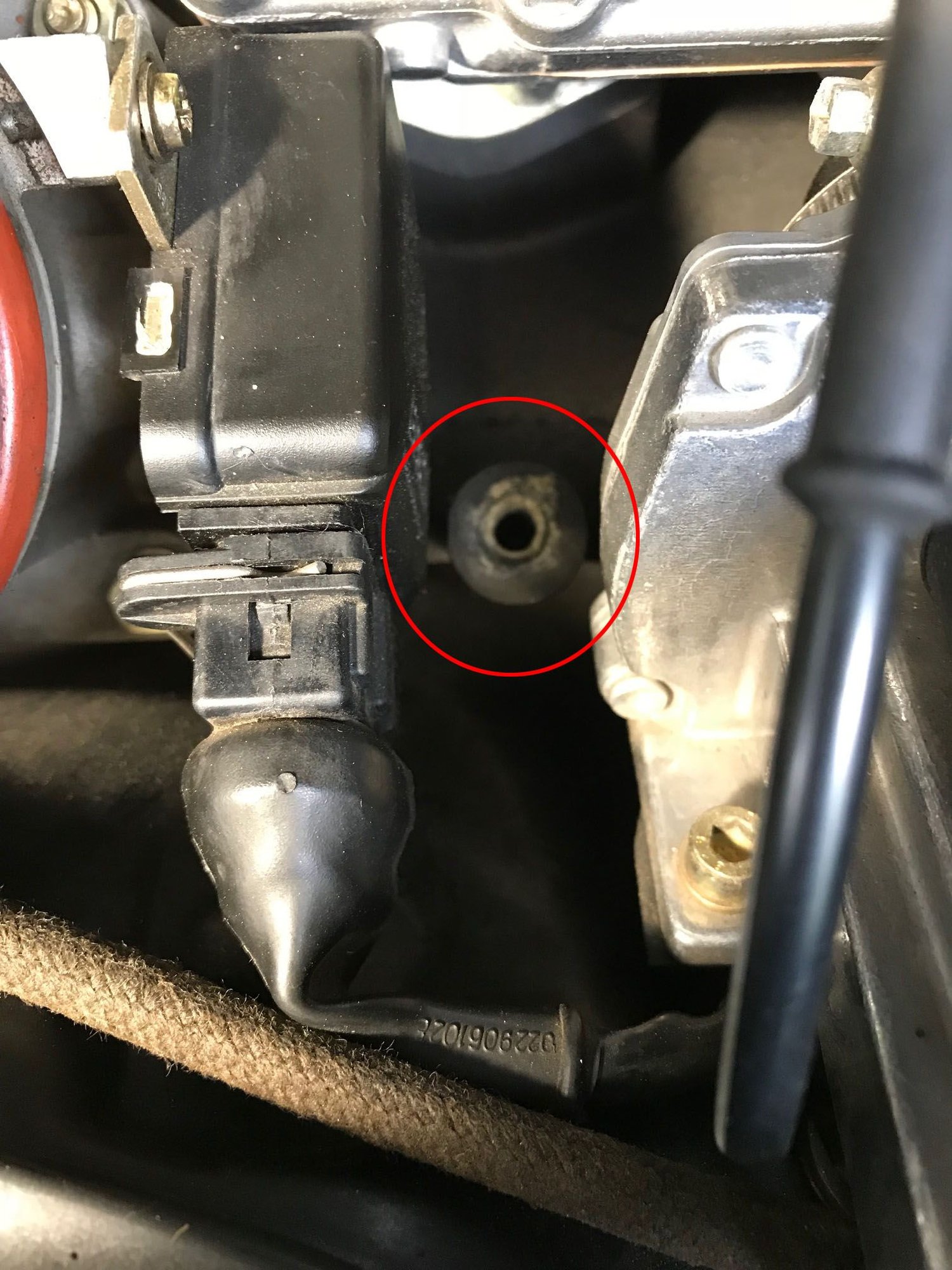
Also just noticed this stud part 99906223402 is missing, any idea what mounts to it when installed? It is 135mm long, so would stand out quite a bit under the intercooler when installed...
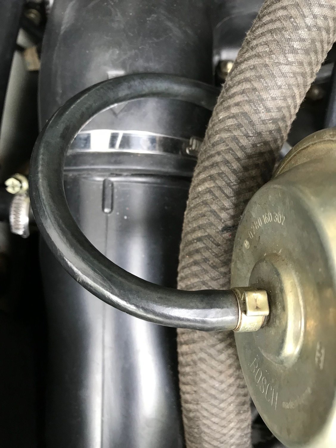
Does this black "VRT" hose look original or no? This also shows the hose (black VRT material) that goes from 3 to 2 then across the engine to a fitting on the left relay panel (and does not connect to 12 or 5).
On my car, all lines in this newer diagram are correct, except:
- The line from pressure regulator to throttle body and then left to a T, does not T on mine. The line connects those two units and then runs all the way to the left of engine bay into relay panel (SEEMS TO BE THE ICU). If this diagram is correct, where does line from the T-out here go?
- The T on far left highlighted splits off to the bypass air valve (12 on earlier chart), pre-empting the idea from earlier chart that 12 should tie into 5 and 2.
- The 4-way splitter on lower left is present in my car and the two lines connecting to it are present and correct in my car. The other two connections from this not shown on the chart - where would these route?
- The highlighted section of 3 short hoses and a T connecting them - where would these route? Possibly the switch-over I started with trying to sort out? Or connecting to one or two of the unknown 4-way connections? ***have since noticed that these are black hoses so they don't seem to have anything to do with the change-over valve/switch (8) which is connected via the "green" braided type of hose.

 06-05-2018, 10:10 PM