When you click on links to various merchants on this site and make a purchase, this can result in this site earning a commission. Affiliate programs and affiliations include, but are not limited to, the eBay Partner Network.
Since I wrote and included oil breather line functions and routes I have significantly changed the breather line route for my engine. With the prior set-up I could not keep oil from migrating into the intake manifold. Since I run a Varioram the oil would collect at the bottom and leak out of the lower seals onto the top of the engine, just did not like.
So I streamlined the breather system, in that I did away with all the oil tank to engine lines except for the one major crank case vent line to the oil tank. There are no other breather lines from the engine or intake going to the oil tank.
I did add a one way valve in the crankcase vent line that allows air out but not back into the crankcase. This creates a negative pressure inside the crankcase which helps control oil leaks. I blocked off all breather lines from the intake manifold going to the oil tank.
From the oil tank I vented only 2 lines and blocked off the rest. These lines are vented to a catch tank that is mounted at the rear of the right rear wheel well. The catch tank has a filtered breather attached to allow pressure reduction in the oil tank.
This set up has stopped oil migration to the intake manifold and also stopped the minor oil deep I had at the front oil seal (due to created negative crankcase pressure.
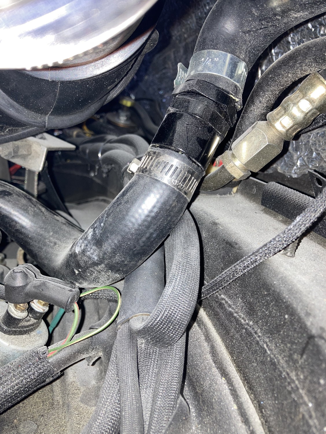
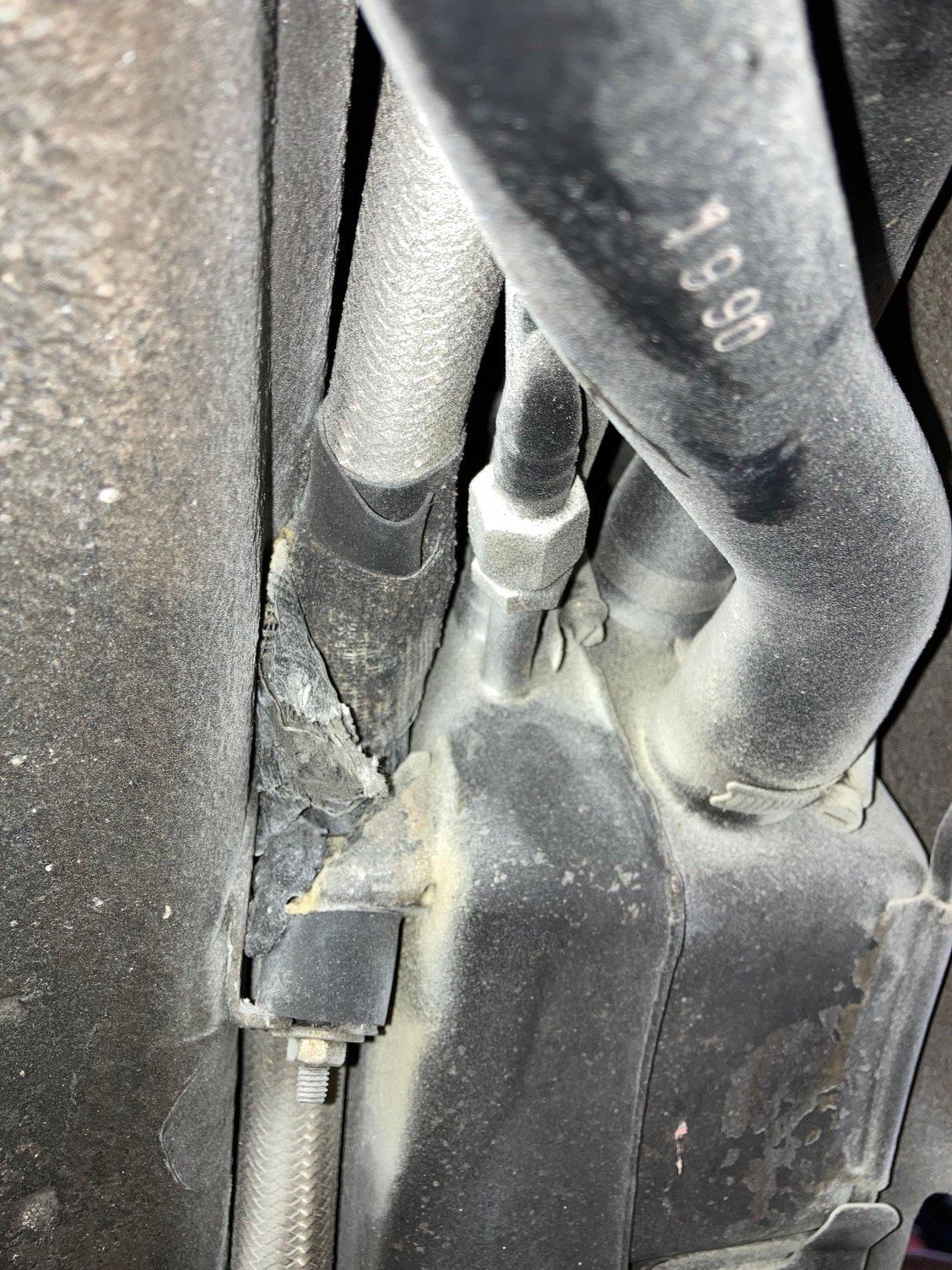
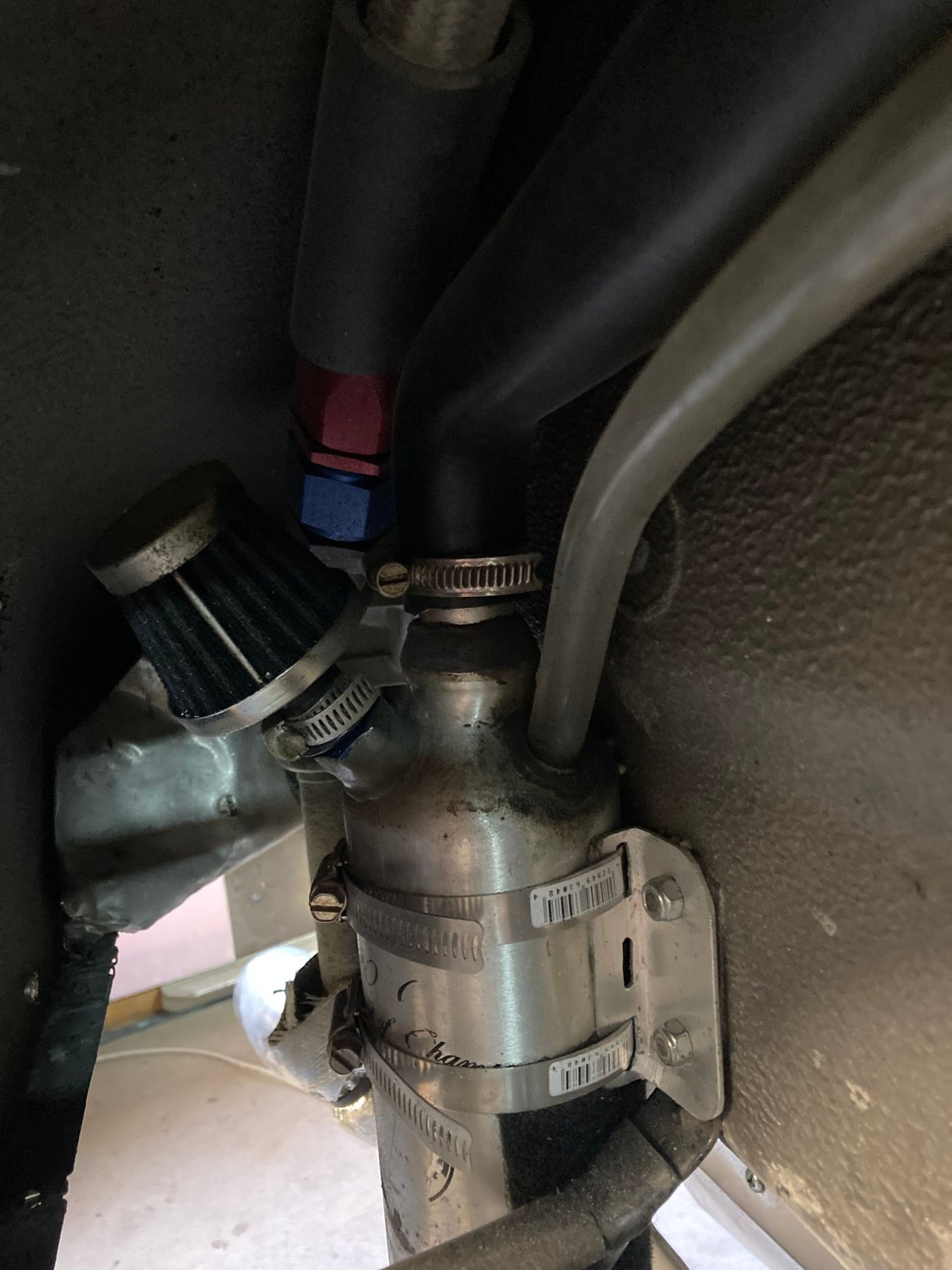
i will attach pictures 1. Of one way valve in line from crank case. 2. Of top of oil tank, confusing picture but you can see the 2 lines going to catch tank, oil return line and crank case vent line. 3. The catch tank, you can see the open breather filter, the main breather line from oil tank and the secondary breather line. All other lines have been blocked off with caps.
Sorry about all the dirt, have been doing a lot of body work and dust is everywhere. You can see the one way check valve in the crankcase vent hose, shiny black . This is top of oil tank showing return oil line and vent lines Catch tank with vent filter, and you can see the 2 lines from the oil tank. These lines run straight back from oil tank follow return oil line down to catch tank.
Nice! Like the catch can location, I was thinking something similar.
Originally Posted by Gus
I did add a one way valve in the crankcase vent line that allows air out but not back into the crankcase. This creates a negative pressure inside the crankcase which helps control oil leaks.
Is this vacuum created from the scavenge pump occasionally pulling air? Have you measured the vacuum pressure? I wonder if it's enough to pull the oil mist back down.
I believe The negative pressure is created by the oil pump removing oil from crankcase. There is no way any oil mist can come back through the breather line as the one way valve stops all reverse oil migration. Oil mist from crankcase can only go one way and that is to the tank. All other lines from oil tank to intake manifold or crankcase have been disconnected and plugged on manifold before and after butterflies. I use only 2 breather lines from the top of the oil tank and these go to the vented catch tank
Great info thanks a lot !
To confirm, both hoses that are going to the throttle body (the one before and after) are going to the breathed catch tank.
The crankcase hose is going direct to the oil tank and on this hose you fitted a non return valve,
Is there any special spec for the non return valve ?
Many thanks
Konstantin
Both lines on the intake manifold ( before and after butterflies) are plugged or blocked on the intake manifold. Both of these lines that are on the oil tank are routed to the catch tank and only these two lines.
The main crank case breather line that goes to the oil tank is the only line left from engine to oil tank. The size of the one way valve should be an AN10 fitting size as this fits inside the existing vent hose and allows a hose clamp to hold in place. Pick an area of the hose that is straight fo about 3 to 4 inches (7 to 10 cm) for valve.
Great, that simplifies a lot and helps tiding up all the hoses,
Regarding the breather hose, I was just wondering if the non return valve had any pressure special specifications
I just started a different thread on basically the same issue. I find this whole thing so confusing. Have fitted ITBs and my 964 has started smoking at Idle and on lift off to an extent. A few times the amount of smoke dumped out of the exhaust has been crazy. Has never been smoky till the ITBs were fitted. From my very basic understanding we run the normal hose from the engine breather (PCV ?) in to the oil tank (I gather this is the normal setup) and then the breather from the oil tank we are running into a catch can as there is nowhere to get it back into the intake.
Im highly suspicious that this is being created by having no vacuum (negative pressure ?) in the system which is then causing the breather not to operate effectively and too much pressure is building up in the crankcase.
The only other random possibility is the top end has suddenly become tired (valve Guides / rings) as I’ve just crossed 100k miles. Still think it just too much of a coincidence that all started happen after the ITB’s.
Sorry I’m a complete numpty on all this.
even if someone could give me a super simple diagram of how best to sort this with ITB’s would be greatly appreciated.
I just started a different thread on basically the same issue. I find this whole thing so confusing. Have fitted ITBs and my 964 has started smoking at Idle and on lift off to an extent. A few times the amount of smoke dumped out of the exhaust has been crazy. Has never been smoky till the ITBs were fitted. From my very basic understanding we run the normal hose from the engine breather (PCV ?) in to the oil tank (I gather this is the normal setup) and then the breather from the oil tank we are running into a catch can as there is nowhere to get it back into the intake.
Im highly suspicious that this is being created by having no vacuum (negative pressure ?) in the system which is then causing the breather not to operate effectively and too much pressure is building up in the crankcase.
The only other random possibility is the top end has suddenly become tired (valve Guides / rings) as I�ve just crossed 100k miles. Still think it just too much of a coincidence that all started happen after the ITB�s.
Sorry I�m a complete numpty on all this.
even if someone could give me a super simple diagram of how best to sort this with ITB�s would be greatly appreciated.
You are venting the crankcase to an atmospheric catch can and you are burning more oil? Have you checked afr? Drained any oil to see what that looks like?
Do you have crankcase vent on top of engine going to oil tank? From the oil tank what lines do you have going back to intake manifold, where and how many? Then what lines from oil tank do you have going to catch can? Do you have catch can vented to atmosphere-
I have NO lines from oil tank to engine intake manifold. Have only the main crank case vent on top of engine going to oil tank. In this line I installed a one way valve to allow air to follow out of crank case but not allow any air from oil tank to flow back to crank case.
if You have any lines going from oil tank to intake manifold either before or after butterflies or slide plates these are probably your oil source which are causing your engine to smoke. - But, all this is just a guess.
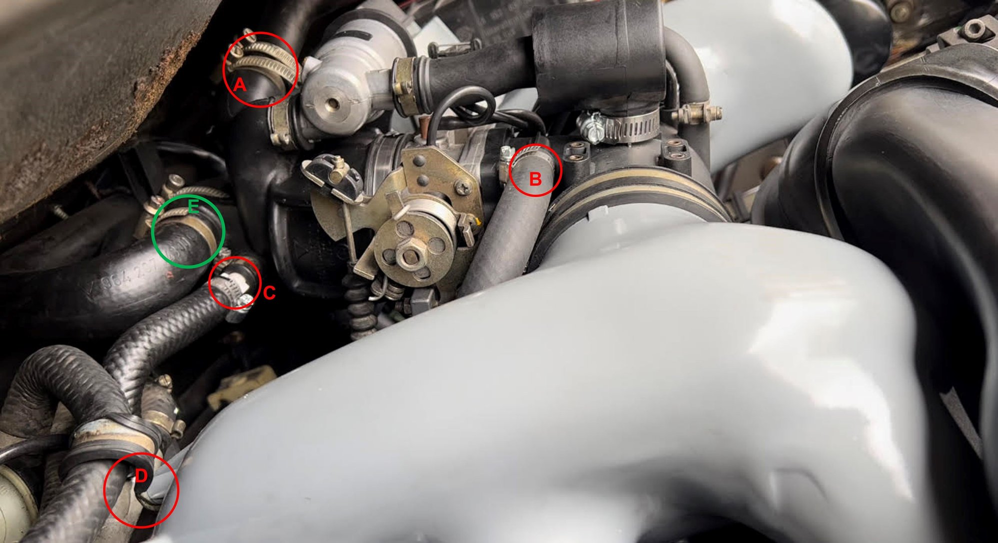
I've tried my best to follow this thread, but I think I'm just not bright enough. I'd like to convert to a catch can solution as well but haven't quite grasped what needs to stay put vs. needs to be rerouted. I believe the green line (marked 'E' is the crankcase vent which needs to stay put). Any assistance with the other lines?
Note: 'D' is not pictured but there is a line that connects to the back of the left-hand side intake manifold. Brake booster vacuum?
A - vents the oil tank (positive crank pressure)
B - vents the oil tank (manifold vac)
C - brake booster (Venturi effect)
D - brake booster (manifold vac)
E - vents crank case to oil tank
A - vents the oil tank (positive crank pressure)
B - vents the oil tank (manifold vac)
C - brake booster (Venturi effect)
D - brake booster (manifold vac)
E - vents crank case to oil tank
Thank you for this! So essentially ignore C, D, & E for this exercise. I believe the parts catalog shows port C capped on the intake elbow vs. connected to the booster line on later models.
I believe I'm getting oil in from A & B, which I'm sure is the result of overfilling. I'm about 3/4 up the level gauge when hot, which I understand is too high.
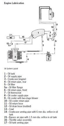
what did you do with lines 14 and 15 as these are the 2 lines from the oil tank that go to the intake (1 before, 1 after butterflies on stock engine). These are the 2 lines that cause oil migration to the engine. Line 17 is the crank case vent to the oil tank, this is the line I installed a one way valve in (air out only).
Did you hook lines 14/15 to the ITBs? What did you do with them?
Thank you for this! So essentially ignore C, D, & E for this exercise. I believe the parts catalog shows port C capped on the intake elbow vs. connected to the booster line on later models.
I believe I'm getting oil in from A & B, which I'm sure is the result of overfilling. I'm about 3/4 up the level gauge when hot, which I understand is too high.
Yeah, you got it. A & B would need to be plugged/capped at the intake. On the oil tank, the smaller vac nipple would be capped and the 1in nipple (0.23� ID) would be vented to a catch can (reference pic in this post: https://rennlist.com/forums/964-foru...l#post16741703 )
Do you have crankcase vent on top of engine going to oil tank? From the oil tank what lines do you have going back to intake manifold, where and how many? Then what lines from oil tank do you have going to catch can? Do you have catch can vented to atmosphere-
I have NO lines from oil tank to engine intake manifold. Have only the main crank case vent on top of engine going to oil tank. In this line I installed a one way valve to allow air to follow out of crank case but not allow any air from oil tank to flow back to crank case.
if You have any lines going from oil tank to intake manifold either before or after butterflies or slide plates these are probably your oil source which are causing your engine to smoke. - But, all this is just a guess.
Thanks to all for the super useful feedback and help.
All along we suspected that pressure was building up in the crankcase and causing oil to be pushed from the bottom end up into the combustion chamber and causing some crazy smoky moments.
In the end it was very simple that with all the fitting, we ended up with a kink in the hose from the breather to the oil tank. The kink was in the wheel arch well out of view.
Problem solved now and no damage done thank goodness.
i still am interested in exploring the one way valve from the breather to the oil tank in your picture in the hope of creating a little bit of negative pressure. Any chance of details of the valve you used, size, spec etc ?

 02-14-2022, 11:05 AM