When you click on links to various merchants on this site and make a purchase, this can result in this site earning a commission. Affiliate programs and affiliations include, but are not limited to, the eBay Partner Network.
You should be reading 12vdc.
Measure the voltage at the red wire or "power" with the same setup as before - you should read 12vdc when switch is pressed and when not pressed.
I measured the power red wire from the switch. Nothing with car off. With ignition to position 2, I read 12 volts with or without pressing the up and down buttons. Also just to be clear, the ground from the relay pin 85 just goes directly to the chasis ground?
The problem is at the switch - you have high resistance in the switch dropping the output voltage when switched. From the drawing it looks like they want you to have at least 2amp 12vdc source to power the switch, so you probably have near that when pressing it.
What is the manufacture and model number of the switch?
Last edited by mojorizing; 12-11-2021 at 03:30 PM.
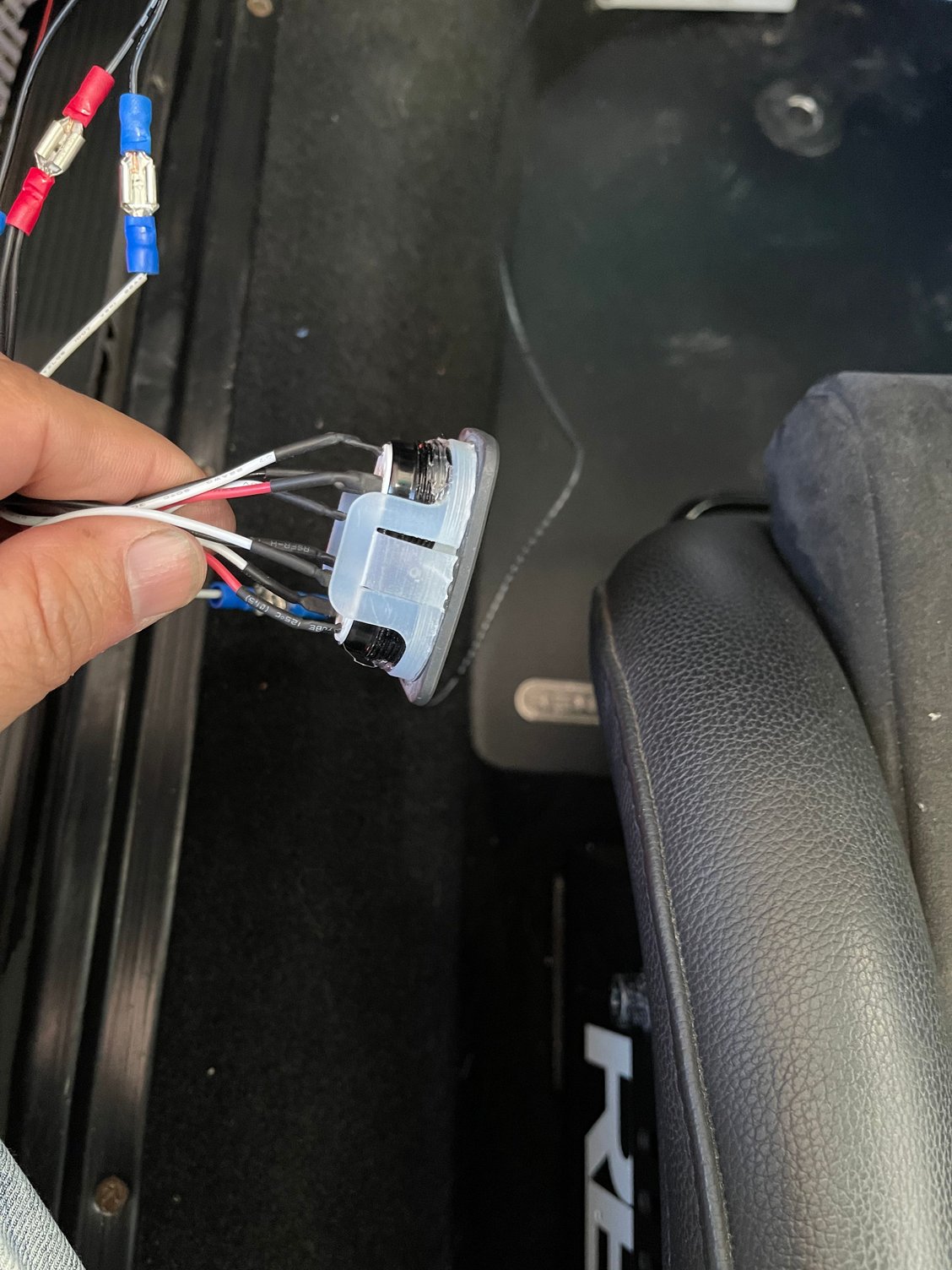
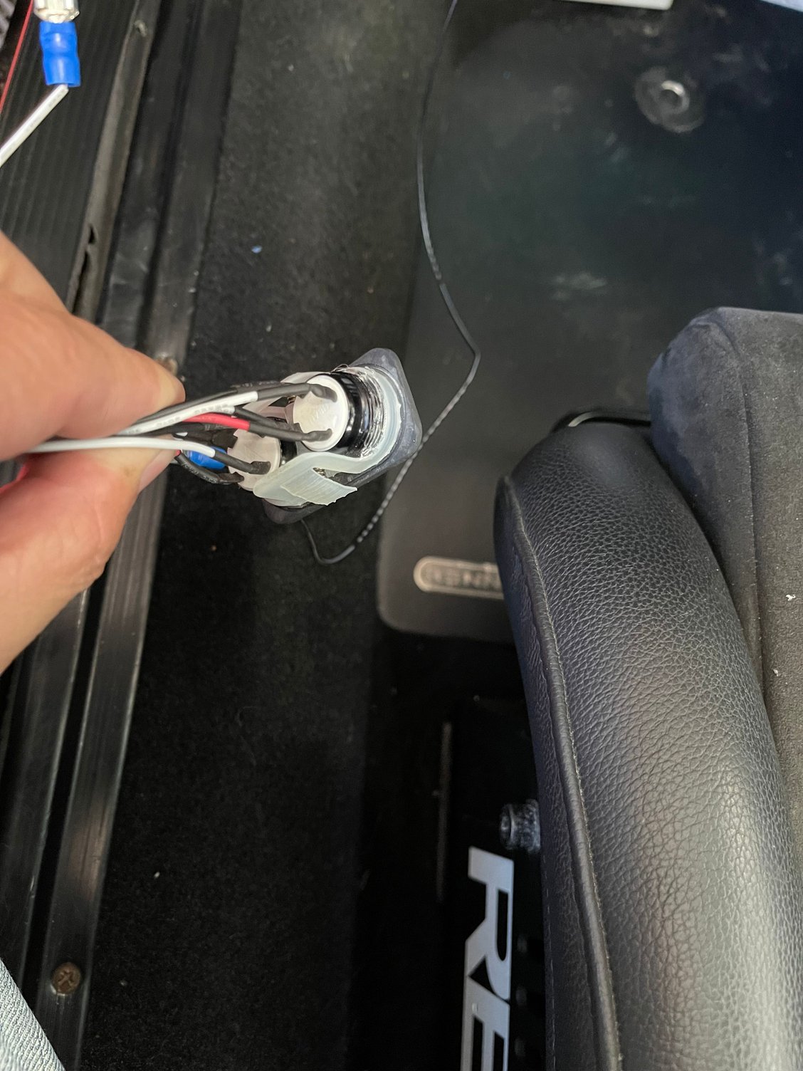
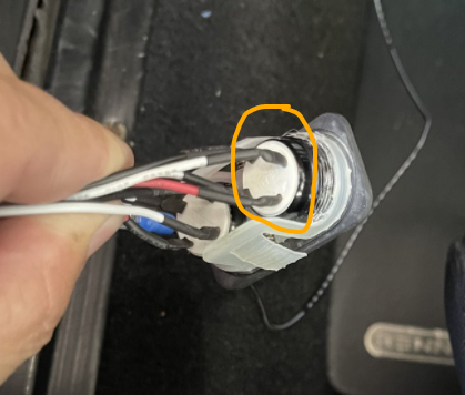
I don't see any markings on the switch itself but here is a picture of the switch. Also the wires are pretty small as you can see, not sure if that has anything to do with it. I will solder and heat shrink everything once I get everything working properly.
Each switch has 4 wires attached to it, 2 white wires and one red and one black wire. The red (+) wires from each up and down button as well as one white wire from each button are tied and heat shrunk together and goes to switched power. The black wires (-) from each go to ground. That leaves one white wire from each button goes to the up connector and down connectors from the solenoids.
Ok, that could be wired correctly , and depending on if it's a SPST or STDP switch, it could be always lit up or lit up and then off when pushed.
But the down/up button should remain on when the up/down button is pressed. Is this the case, that when you press one button the light goes off, and the other button goes off too?
I don't think the other light should go off when the other button is pushed. It''s going off because oof the reduced voltage when the other button is pressed. The cause for this could be the solenoids aren't rated for 12vdc service but this is unlikely. However, is there any information on the bodies of the solenoids - rating , manufacture, etc.?
The other cause would be the switch is wire incorrectly. You can try unplugging the coneectors that go to both solenoids, then press the buttons while again measuring the voltage at the disconnected wires that were going to the solenoids, yuo shouls see 12vdc when pressed, and the other light not going off.
Something interesting happened. I disconnected the up and down wires going to the solenoids and then actuated the switch and the lights stay on both buttons. With the wires still disconnected, I checked the volated of the up and down wires coming from the switch itself and both read 5.4 volts when pressed. When I check the other end of the connector going to the solendoids when pressing each up and down button, I get zero voltage. Is that what you wanted me to do? I may have misunderstood.
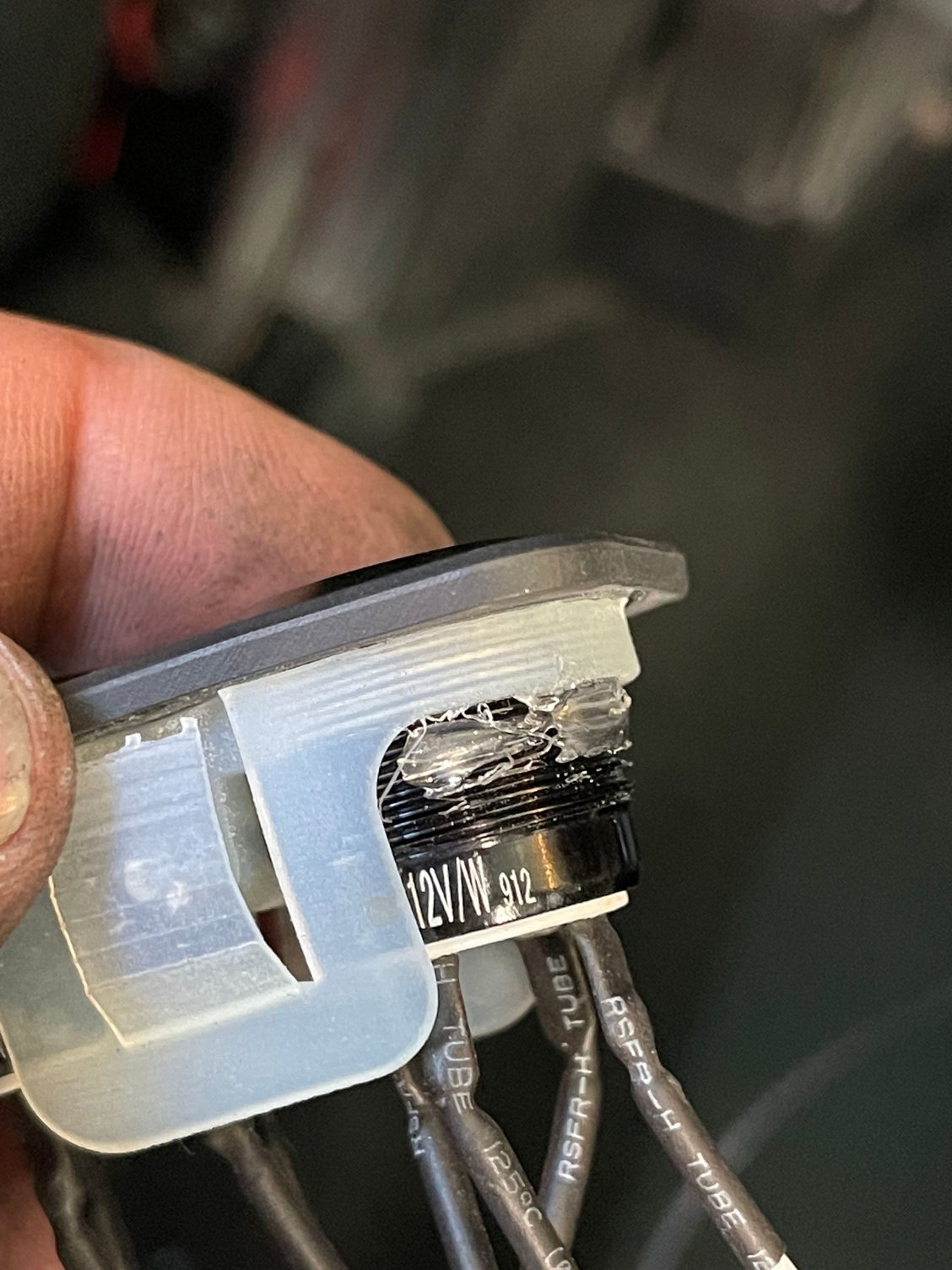
Yes, that's what I needed. I would say the switch wiring is incorrect. Without the pin out or schematic of the switch it makes it hard to troublleshoot. On the black body of the push buttons I see "12vdc" is there anything else?
As a final check on the solenoids, and with the solenoids disconnected, you could power them up simply by directly wiring a jumper from the + of the battery to the wiring of the solenoid pairs. And if you want, your meter will read up to 10amps DC. Put the selector switch to 10A dc amps, move the red lead over to the 10A port, then connect the meter in series between the jumper and the solenoid connect. That will get you the amp draw of the solenoids.
Your meter has no fused protection at 10 amps, If "1" is on the display then solenoids are drawing more than 10 amps disconnect the power immediately.
Last edited by mojorizing; 12-11-2021 at 05:35 PM.
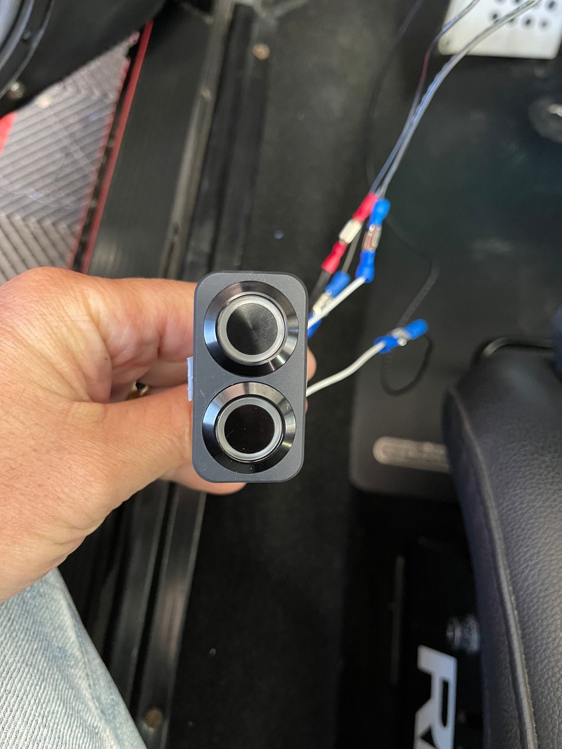
So I checked the solenoids by directly connecting to the battery and they are working. The car raises and lowers so they are working well. I think the problem is within the switch. Could they have wired it wrong by accident? I am not sure how I would try to wire it differently. BTW I truly appreciate all of your help. If you ever come out to San Diego, hit me up and I will buy you a beverage of your choice. Here is a picture of the switch up close.
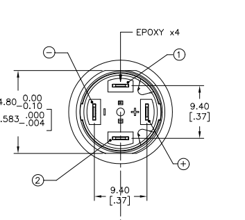
It's unlikely that both switches are bad. I suspect that they recently changed to push buttons and you got a beta version of the kit - probably the wrong illuminted push button for this application. Four wire push buttons are straight forward wiring. The drawing shows a rocker switch, not push button. Call them and tell them all the troubleshooting steps you have taken. The good news is that you know the compressor, the solenoids and the blow-off valve works!
Let us know how they resolve your problem. I'm also interested how well it works on a 964.
Thanks for the offer of a cold one!
Last edited by mojorizing; 12-11-2021 at 06:17 PM.

 12-11-2021, 02:38 PM