ABS Short Check
#1
Rennlist Member
Thread Starter
Join Date: Jul 2003
Location: Peachtree City, Ga
Posts: 1,948
Likes: 0
Received 63 Likes
on
53 Posts
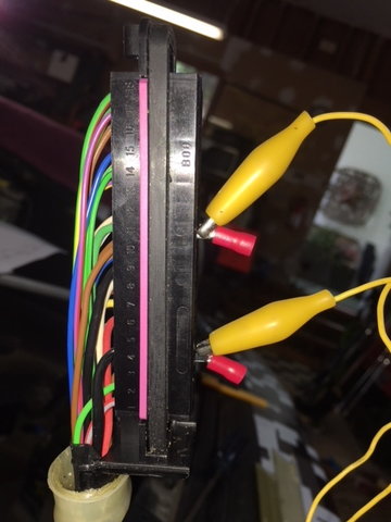
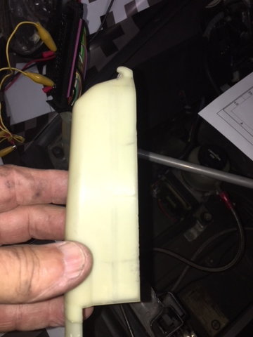
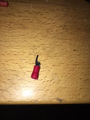
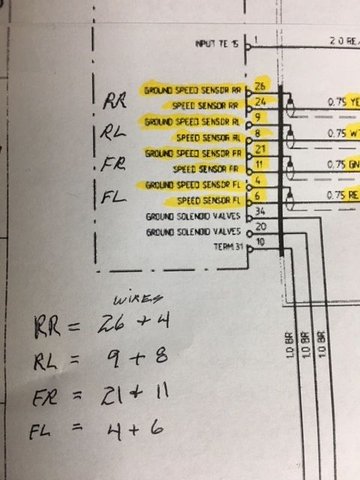
I have had issues with my ABS system for a while. I purchased an ABS Test System from Michael *** (member) and it is really a nice piece of kit. Ran all the test with it but could not find my problem as it was an on and off failure. Decided to live with it for a little while. Finally failure became very persistent and I knew I had to figure out issue. Know that the test set showed all to be functioning properly, I figured that it had to be a major short or a wire break. One thing I did notice was that the ABS failure was usually preceded by and pad wear warning light. Which in my case could not be as I had removed all brake wear sensors. So I decided that I needed to find the short. First, I had to find the short in one or more of the electrical lines going to the wheel sensors. To do this I needed check for continuity from the ABS computer (using the right pins) for each set of wires going to each wheel. (See the electrical diagram showing correct pin numbers for each wheel). I disconnected the battery, and unhooked the ABS head from the box. Looking at it I could not see any numbers that depicted the pin number location. I realized that the large white plastic back cover had to come off of the connector to see the numbers which are under this protective cover. Once cover is removed you cna see pin numbers very clearly on side of connector. Find the 8 pin points or wires that you will need to use. FL = 4&6, FR = 21&11, RL = 9&8 and RR = 26&24. ** NOTE on the picture of wire diagram I show RR as 26 & 4 BUT it should be 24 as show in the diagram itself. I used a modified electrical fitting to slide into the wire/pin position and then an alligator clip to hold my wire connection.
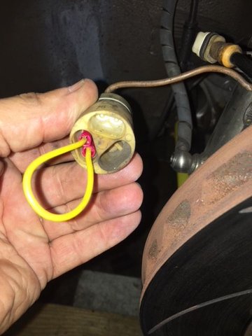
At the wheel you need to disconnect the wires going to the speed and the brake pad sensor. This is a large white cylinder shaped plug which has a black wire going in at one side and then 2 connectors coming out - 1 to speed sensor , 1 to brake pad (2 small wires) . To check for continuity from the ABS computer connector to the sensor you need to make a wire connection that will fit on the 2 pins down inside the white cylinder shaped plug - it will be the connection with the rectangular fitting. Here I used to standard wire connectors that you can crimp to a short wire ( one on each end) then slide down on the pins using needle noise pliers. Note - use pliers to install and remove connectors as fitting is tight. Start on a wheel of your choice I picked left front. Once the short wire link is installed go to the ABS connector that you have opened and find the correct pin locations, Front Left is wire/pins 4 & 6. Insert wire clips, use alligator clip to each wire and run a continuity check. Don't just look at it and say OK continuity checks. Grab the white cylinder and move the black wire on the back side around a lot wiggle it up and down hard and see it continuity is maintained. If it is then the line is good - if it breaks thne there is a short in the black wire and the whole line needs to be replaced. I found one at Pelican ( No Affil) for $275, but saw some as high as $350. See pictures to give you a better idea of what I am talking about, may help clear up questions.
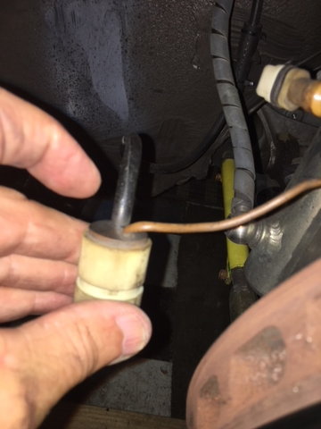
In my case it was the RF wires that had gone bad. On first look the meter showed that I had good connection, but when I started wiggling the wires everything went south fast. (See picture with finger pointing at were wire is broken) I striped that black main cover off the wire to get to the 5 smaller wires inside to determine what was broken and where. There were 4 wires that were broken, only one was good as when I pulled on each wire the plastic cover just separated. With the one good wire it held.
Order of Pictures is:
1. ABS Pin connector showing top removed and number for wire locations plus wire clips used
2. White cover that needs to be removed to find pin numbers
3. Wire connector used/made to link both wires from ABS unit
4. White cylinder - plastic molded unit - not finger points to area were wires had broken
5. Small electrical "U" connection _ cut off one leg to slide into pin connector
6. Wire diagram clip showing pin numbers you need to cross to check continuity once wheel sensor connection is crossed.
Hope this helps someone -
#2
Congrats! I'm suspecting this will happen sooner or later to some of us. I have previously looked in to replacing the ABS wire harnesses and was shocked by how expensive they are. As this is just a simple sealed electrical connection and the failure point is on the end of the wire harness, surely there must be a cheaper solutions to remedy this.
Thanks!
Andrew
Thanks!
Andrew

