When you click on links to various merchants on this site and make a purchase, this can result in this site earning a commission. Affiliate programs and affiliations include, but are not limited to, the eBay Partner Network.
I am replacing the crumbled plug on the end of my crank sensor in my '92 C4. All literature I have found indicates that the three sensor wires are to be connected as follows:
White is #1 in the connector
Brown is #2
Shield is #3
However, on my car, the white and brown wires are reversed. I took a photo of the crumbled connector before I disconnected it and thus I know which colour wires went to which position in the connector. Just to be sure, I checked the connector on the car's main harness and it was wired to be compatible. In other words, white to white, brown to brown and shield to shield. This confirms that for some reason my car is backwards which does not make sense unless polarity on this sensor does not matter.
In searching rennlist for answers, I learned that this sensor is an inductive sensor and one poster said it does not need power because it is a generator. Well, a generator makes DC power, so polarity might be really important here. I don't want to damage the DME by sending reverse polarity to it.
Has anyone seen this problem before? What should I do? I should point out that this car has not run for over 15 years so I cannot say if it was running and then suddenly stopped or if anyone else worked on the crank sensor.
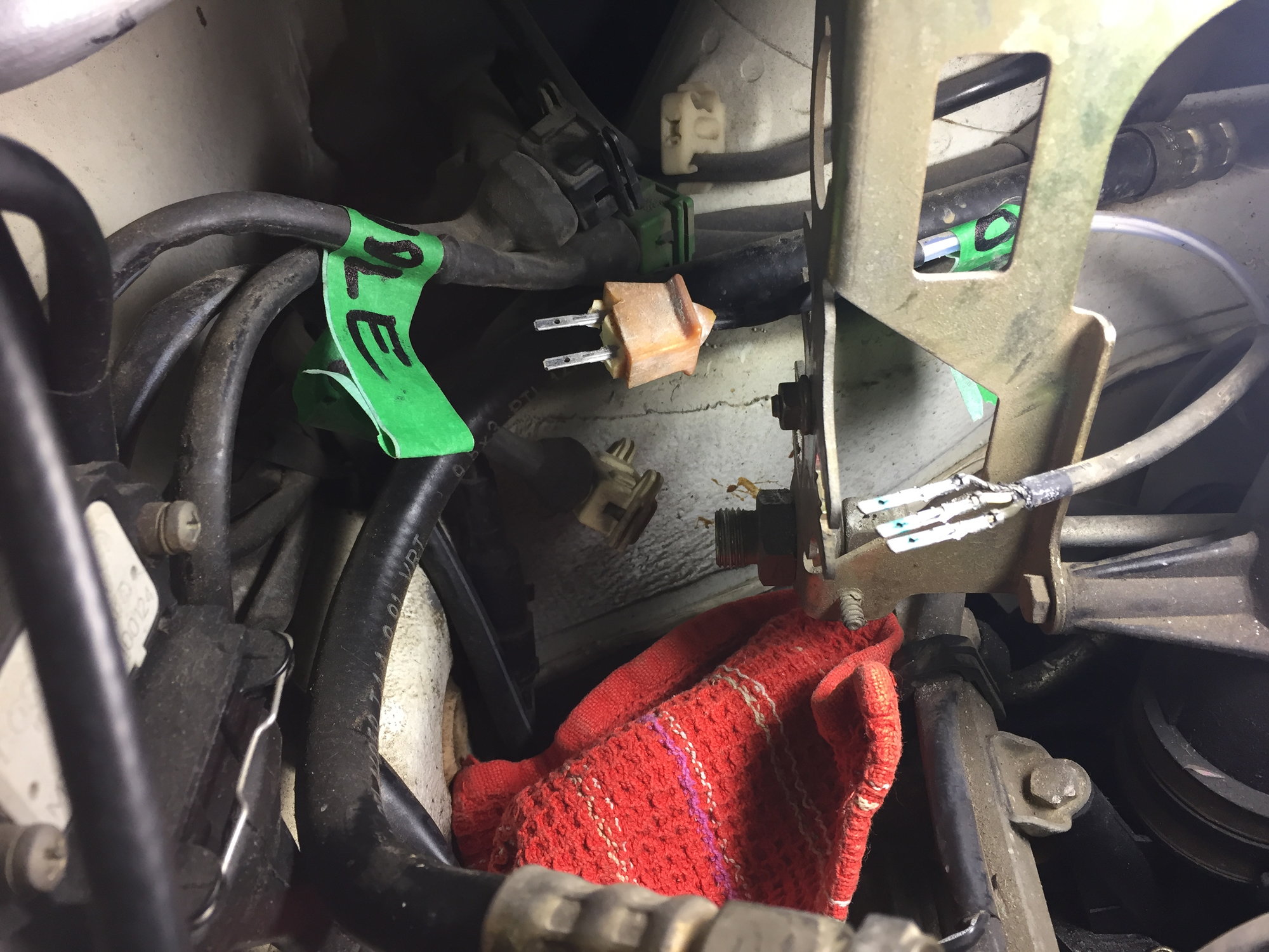
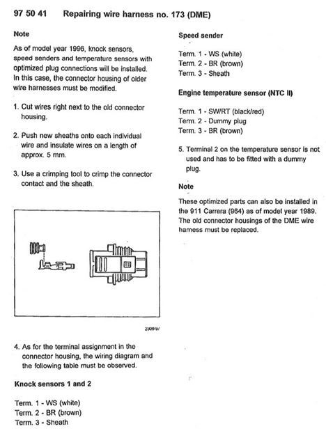
I have included a picture taken of the bare wires and tabs that remained after the connector itself had disintegrated. These wires go to the crank sensor or at least I believe they go to the crank sensor as it has 3 wires as opposed to 2 wires and was connected to the BLACK connector on the harness. The other two connectors are WHITE and GREEN. As I understand it, these connector colour codes identify the three different sensors where BLACK is the crank sensor. As you can see from the photo, the middle wire of the crank sensor is white and my wiring diagram says it should be brown. I have also attached the Porsche instructions on swapping to the new style plug (Document 993 KD-NR. 97 50 41. This document clearly shows white is position #1 and not in position #2. So my white and brown wires are reversed.
I am almost ready to try to start the engine, but really need to sort this out first. If anyone can offer any advice or show where I might search for answers it would be greatly appreciated. This is my first Porsche having acquired it in March and after months of work am anxious to get it running.
If it�s the same sensor and you are sure of the orientation, I would just reconnect it as found. It�s only 3v and will have a low amperage. I doubt it�s going to blow the DME ECU. The engine will either run or not. If not, reverse one and two and try again.
You will note that the test procedure details the polarity of the oscilloscope leads. Maybe test before running the engine if you want to be extra safe.
You will note that the test procedure details the polarity of the oscilloscope leads. Maybe test before running the engine if you want to be extra safe.
Thanks John,
I don't have a scope but can probably borrow one. I have read and researched this until my brain hurts. Some say polarity matters for this sensor and others say it does not. Due to its construction, this sensor has to output AC voltage so polarity may not matter. But if the sinusoidal waves that the manual talks about are from say +5 volts to -5 volts then the DME might not be pleased if the polarity gets reversed since that could throw off the timing by one flywheel tooth could it not? Theory here is that as a tooth approaches the sensor, the output voltage increases until the middle of the tooth is directly below the sensor, and then the voltage decreases until the middle of the tooth space and then begins to rise again.
Still, if the timing is off by only one tooth, I would think the engine would still run. With 129 teeth, being off by one tooth is less than 3 degrees but of course I would want to make sure I have it right. The question is how would I know if it is off? I have no benchmark to compare it to.
You can check the the flywheel speed sensor with a multi meter.
To test this, you open the DME (under drivers seat) and used a multimeter set to AC voltage, across pins 47 & 48 of the large plug. it's supposed to read 3 volts. Mine was 0, so needed to be replaced.
So, if you have less than 3 volts, either your wiring or your sensor is bad.
Thanks John and Steven. Sensor tested good. Despite the conflict, I wired it as I found it and the car started and seems to run ok at low rpms. Higher rpm testing will have to wait until after an oil change.
My concern about the wiring was driven by two things. The first was the obvious colour conflict and the other was due to the fact that the connector had completely disintegrated and left only the bare metal tabs.
If these tabs had fallen out, the previous owner may have re-inserted them into the wrong slots.
You can check the the flywheel speed sensor with a multi meter.
To test this, you open the DME (under drivers seat) and used a multimeter set to AC voltage, across pins 47 & 48 of the large plug. it's supposed to read 3 volts. Mine was 0, so needed to be replaced.
So, if you have less than 3 volts, either your wiring or your sensor is bad.
Hi Guys,
So have fitted the new 996 style sensor, and set the gap to 0.9mm, but car still not sparking, although I do get a spark on the coils when the ignition is first turned on.
When truning over, nothing.
Tried pin 47 & 48 when truning over with a multimeter, and nothing.
So do I need an oscilloscope?
What else can I test to see if the sensor is working?
How or where can I get my ecu tested?
When it first started playing up, it was a bit intermittent on starting with the occasional back fire.
Any help and guidance greatly appreciated,
Thanks,
Steve