

MAF error from air leaks
 07-23-2015 | 05:35 PM
#1
Thread Starter
Rennlist Member
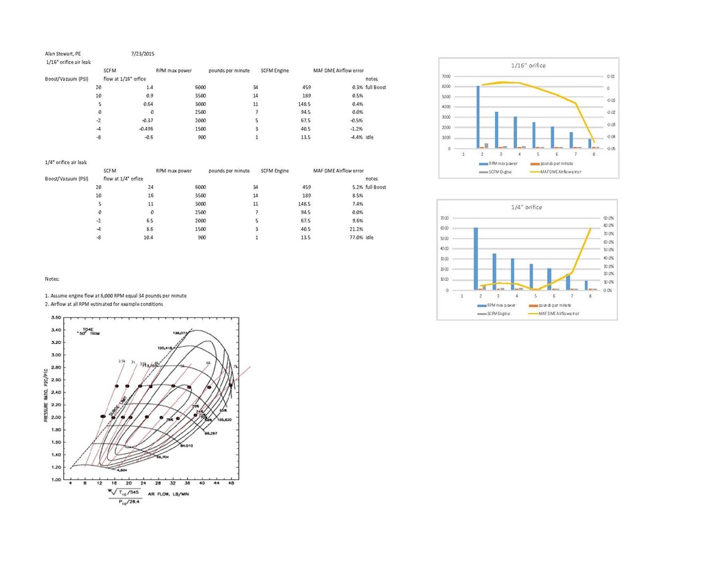
I was considering the impact of air leaks and how the AFR changes. I put together this analysis that shows the real affect from air leaks to be when the engine is in idle to part load, below 1 Bar absolute. In boost situations the allowable air leaks are so small (say 1/16" orifice) that the lost air has little effect on actual AFR.
Now there can be some transition losses on boost, say if the brake booster check valve is not working. There would be additional airflow not in the combustion cycle. This applies also to the dual chamber waste gate and HVAC accumulator.
Bottom line, small air leaks are not driving the wide AFR swings we are seeing with MAF installations. Part of the analysis, comes to the most reliable real time sensor, and that changes in our micro time periods. (When approaching sensor triangulation, agreement of the engine parameters, at high load factors, a little rich is safer than lean. Having said that, once we establish the trusted sensors, correct AFR values are best.) What I mean is that at low speed (RPM) the MAF can have more error, and at high speed the O2 may react to slow. So who do we trust? I think there is a hand off to MAF, based on MAF credibility for WOT.
The turbo map shown is not my work, but included for clarity of the analysis.
Thoughts?
 07-29-2015 | 06:45 PM
#2
Thread Starter
Rennlist Member
I was a little surprised that no one commented on the analysis. Given that the work reveals boost leaks have played negligible part in the MAF conversions Pig Rich issues. And as Joshua determined the big swings were AIT and MAF related computational errors. There may be additional MAF issues with the approach angle for the inlet air flow. Air does have mass, and does not turn corners well, at least not uniformly.
Given the MAF is located just after a 45 deg turn in the inlet duct, we can expect some stratification across the sensor plane. In fact as the sensor installation bisects the inlet angle, the mass flow toward the sensor mount will be higher than at the inner radius of the angle.
The OEM go to great length to prevent angular velocity components into the MAF, or use a multi-point mass flow measurement.
I support Joshua's work product, and recognize there may be more tweaking a of the flow tables or alternate MAF device for accuracy.