When you click on links to various merchants on this site and make a purchase, this can result in this site earning a commission. Affiliate programs and affiliations include, but are not limited to, the eBay Partner Network.
I was focused on scaling the 5k, but see your issue now with the large steps at low resistance. I suppose one ham-fisted way would be to use small handful --say 5-- digital pots in parallel so that you can effectively get a 1k digital pot (with 5 times the current capacity, which may also help). Or, maybe a more "elegant" way would be to replace the fixed resistor with a second digital pot, so that you can program both to generate smaller total resistance steps on the bottom end? I haven't played with the numbers, so just conjecture -- and if the resistance starts getting very low you may blast past the current capacity of the pots this way...
Not elegant, but playing with the numbers it seems you could have one digital pot with a parallel 300 ohm resistor producing the results in your chart. You could then run that in parallel with another digital pot to get smaller steps at low ohms. You'd set the first digital pot/fixed resistor to a lowest resistance higher than the desired output. Then you'd set the second pot to reduce the resistance a little as needed to get where you want. In your spreadsheet, for example, if you wanted 41 ohms, you'd set the first pot to 3 to get 48.9 ohms, then you'd set a second digital pot to 13 so that it makes 252.9 ohms. Then when you run these in parallel you got (48.9*252.9)/(48.9+252.9) or about 41. If you wanted 45 ohms, you'd keep the first at 3/48.9 ohms and set the other to 25 or about 500 ohms.... Just brainstorming, not saying it works necessarily..
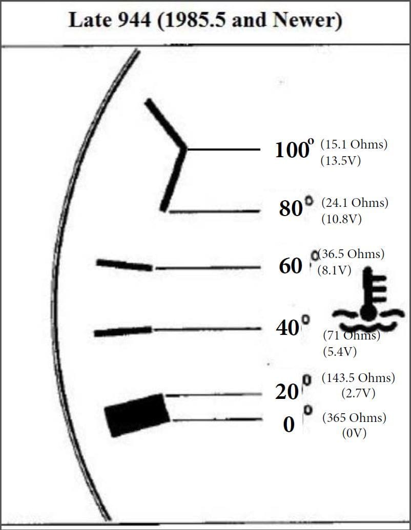
Okay, so I went out and measured the exact resistances required to hit the desired marks on the temp gauge with the DC-DC converter ("alternator") running to give me 13.5V instead of 12.5V from just the battery, below is what I came up with.
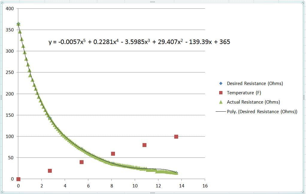
Based on this, I used Excel to graph these values and give me the formula for the resistances I would need between my measured values. Below is what I got.
Using two 5k digital pots and a fixed 500ohm resistor in parallel, I was able to create most of the resistance values I would need. The only area I don't have quite the "resolution" I'm looking for is between 18 and 28 ohms, but not a big deal. Attached shows all the resistance values I need from 0-100 Celsius, and what I'm able to create with the digi-pots. The yellow highlights are the fixed values from my measurements, the red highlights is where my controller de-rates the current allowed (too hot), and the green highlights show where I'm not able to accurately recreate the resistances I need.
Now I just need to start playing with the Arduino to see if I can make this actually work. Should be fun...
Great work there. You might check the current draw of that gauge to see if the digital pots can take it. I suppose you can always add more pots in parallel to help with both the current and granularity. I'm not sure how many "steps" you need to make the gauge look smooth, but you could also use a multiplexer chip or two with the arduino and use (for example) 32 different resistors of just the right values wired to ground. If you're not familiar, a multiplexer is like a digital **** with one output and multiple inputs, and you use the arduino to tell it which input you want connected to the output at any given moment. The current limitation then becomes dependent on how much the multiplexer chip can flow, which is generally way more than a digital pot. I had a 2011 BMW and could see the temp gauge moving in small fixed increments like this. With enough steps, you'd never know it wasn't driven by an analog signal -- the BMW looked smooth, but it you watched it closely you could see that it really only had maybe 32 positions give or take....

 03-31-2015, 07:10 PM