When you click on links to various merchants on this site and make a purchase, this can result in this site earning a commission. Affiliate programs and affiliations include, but are not limited to, the eBay Partner Network.
OK I am taking off my manifold to remove the hard pipe tree. I am also going to fit my Laust Vacuum manifold(5 outlet model). I am using a turbosmart e-boost controller on a Tial F38 in DP set up, CEP fuel rail, and M tune, so I just want to confirm that this is the right diagram ? I am only concerned with red lines in diagram, as Tail in DP mode is set up already and working as designed(green lines)
So I would hook up the vacuum ports from Laust's VM to
1. FPR
2. Diaphram thing(on right) and from there to throttle body
3. M tune map sensor
4. Blow off valve
5. Factory vacuum storage canistor thing where the battery is on US spec cars
* Also Keeping banjo line going to KLR
If I do this as above, I will still need to T off the brake booster line to heater check valve, unlike the diagram above ?
TIA
Last edited by Cyberpunky; 11-08-2014 at 04:06 AM.
Bruce
For the longest time I was told that that diagram on Lindsey's website was incorrect ... But that was yrs ago
I think if you do a search ( not to sound like you know who... eehh Reno )
You may find a post, correcting what was wrong with the orig Lindsey diagram?
My BOV has its vac line going to the Fuel Damper on the front of the fuel rail
Sorry I couldn't be more help
Also that diagram looks to be a 2 port WG
Do u have that ?
Regards
Ed
I can't say for sure, but I've been looking at these diagrams a lot lately and considering a manual boost controller. I think your controller needs to inturupt the line between the IC pipe and the "T". If you go here and click "TECH" there are instructions that might be helpful. They were to me.
I have tial running in dual port set up. I am trying to get rid of as many *T* connectors as possible. The laust vacuum manifold has 5 outputs plus klr output. Just want to make sure my plans above are best way and correct
The tial I believe has the reverse order, if I am not mistaken
As for the T's I hear ya ... I thought I had a leak ( low vac ) actually still have low vac #'s ( like 16 when warm) so I removed the Laust set up and used like 3 T's just to see if it changed things ... It didnt
I dont know if the CEP fuel rail has a fuel damper ? but that is where one T is from the BOV fuel damper and the banjo bolt where the Laust thingie would go
Cheers Ed, yeah I have tial working properly so not concerned about that part of diagram. The fuel rail doesn't have a vacuum controlled damper like factory rail.
Thanks Mtnman. My Tial is hooked up already and working properly so not worried about that part of diagram. My concern is how I am hooking all the other(red) lines. The diagram doesnt show vacuum storage canistor, so is there anything else I need to T off too ? is my list above complete ?
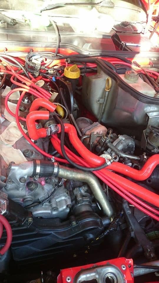
Well got my vacuum lines done today.
Sort of used this diagram, except I took vacuum to blue check valve from brake boost line, as I also had Lausts brass joiner and wasn't sure if I could get a clamp on brake booster back on if I undid it, so had to keep the section to from brake booster to the joiner.
also fitted AOS line and venturi delete, with the Laust vacuum manifold

 11-06-2014, 06:23 AM


 )
) ")