
Help with Venturi Delete/Vacuum Lines
 10-26-2013, 08:51 PM
#1
Pro
Thread Starter
Join Date: May 2009
Location: If it's the wknd, I'm at a track...
Posts: 666
Likes: 0
Received 0 Likes
on
0 Posts
Well finally have dug into relacing the vacuum lines and doing the Venturi Delete. But I have to admit, I'm just not the brightest bulb on the Xmas tree when it comes to things automotive.
I have everything apart i.e. intake manifold off (as you can see for the pic in the next thread) I have the LR Venturi Delete Kit, I've read their site instructions on this process as well as gone over the "Offical Venture Delete" thread here on RL. And I can't for the life of me figure out which hoses goes where and what gets deleted. In the LR kit, for example, there is a lonngggg hose and relaces something and I can't figure out where it goes i.e. where it starts and where it ends.
And there are a couple of other shaped hoses in the LR kit and I can't figure out where those goes either.
Can anyone help?
TIA
 10-26-2013, 09:06 PM
#4
Pro
Thread Starter
Join Date: May 2009
Location: If it's the wknd, I'm at a track...
Posts: 666
Likes: 0
Received 0 Likes
on
0 Posts
I did. Multiple times. In fact I keep looking at the pics & diagrams and it makes no sense to me. I am just NOT understanding what gets deleted and where certain hoses go.
10-26-2013, 10:02 PM
#5
Rennlist Member
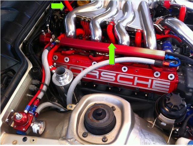
Start by covering those intake ports. If/when something falls in and gets past a valve, you'll be sad.
Not sure where you're lost, but I marked your picture in red to show where the venturi is. Pull that out and connect one of the ports between the intake runners to the I/C pipe port and connect the other port between the runners to the brake booster.
Not sure where you're lost, but I marked your picture in red to show where the venturi is. Pull that out and connect one of the ports between the intake runners to the I/C pipe port and connect the other port between the runners to the brake booster.
10-27-2013, 11:54 AM
#6
Pro
Thread Starter
Join Date: May 2009
Location: If it's the wknd, I'm at a track...
Posts: 666
Likes: 0
Received 0 Likes
on
0 Posts
Yes, I certainly would be sad! That said I had pulled out the (clean) rags I had in there just for the photo, to make it a bit easier to see where I was at. And Travisgreen was kind enough to speak with via phone to clear up where I was confused. I have to say that while I really like LR and the products I have purchased from them have always been of high quality, the lack of instructions on some of these things is really sad. Some of us don't pickup the mechanical stuff as quickly as others.
Anyway it's been good to pull everything apart as as I was able to also replace the oil seal on the top of the turbo (I think it had been leaking just a bit) and I see my injectors are in need of replacement also. In fact I wouldn't be at all surprised if the injectors are a major issue in my (still) ongoing running rich condition. And the vacuum lines, with just a couple of exceptions, were in better shape than I had anticipated they would be in.
Will be back under the hood to put everything back together today. Hopefully all goes reasonably well...
Thanks again to the great folks here that are so helpful.
Michael
10-27-2013, 01:18 PM
#7
Pro
Thread Starter
Join Date: May 2009
Location: If it's the wknd, I'm at a track...
Posts: 666
Likes: 0
Received 0 Likes
on
0 Posts
Can anyone tell me what this should b connecting to? The first pic is of the broken, not connected end and the second pic shows where it connects to the J boot. (It's the cloth covered line going into the J boot)
Trending Topics
10-27-2013, 03:11 PM
#8
Rennlist Member
It goes to your cycling valve (boost solenoid). Is there a little plastic barb broken off inside that hose? The plastic ports on the cycling valve get brittle over the years and often snap off like that. Not much you can do to salvage the valve once the port snaps off. (Best bet for getting the hoses off an old cycling valve is to split the hose with a razor, as any real twisting and pulling will snap off the ports.) If you go to an aftermarket boost controller, you can ditch the factory cycling valve (most manual boost controllers actually cost less...)
10-27-2013, 03:15 PM
#9
Rennlist Member
Also, do yourself a favor now and replace the connector that is frayed in the second picture (TPS probably)... Those connectors are available new from places like Eagleday, and will save you a ton of headache, as intermittent harness failures can be some of the toughest to track down...
10-27-2013, 03:19 PM
#10
As I'm sure you have figured out by now, the long pipe in the kit connects the brake booster to the intake manifold. The multiple curvy end snakes under the manifold to plug into the middle port and the simple 90 goes on to the brake booster.
The line from the manifold to the icv should be obvious, and the other longer piece will need to be fitted to run from the icv to the pipe.
I had to cut the long pipe from the brake booster to the manifold, and remove about 1.5 inches. This made it fit better, and let me put that t in, that shows up in the diagrams. I didn't have to alter anything else. I took out the metal piping that's all welded together (from your pics) and bought the aos hose replacement kit from Lindsey. I had to reuse the largest of metal pipes on the welded bunch, which took some machining, but there are other ways to skin that cat.
Make sure you are using he right diagram, be patient and stare at it for an hour, go look at your engine and visualize, then go back to the diagram. I had to get my pieces slowly, but it will come to you soon.
10-28-2013, 10:30 AM
#11
Addict
Lifetime Rennlist
Member
Lifetime Rennlist
Member
Here is a pic that may help to show the brake booster hose. That's the really loooooong one with bends at each end. You will have to cut it in half near the firewall to install the plastic "T" for the HVAC control vacuum line to attach. I don't have a pic that shows the T, but you should be able to reference your old brake booster hose for that.
Also, if you have a specific new/replacement parts that you can't figure out where they go, post more pics and I'm sure that we can help you out.

Also, if you have a specific new/replacement parts that you can't figure out where they go, post more pics and I'm sure that we can help you out.
10-28-2013, 02:07 PM
#12
Pro
Thread Starter
Join Date: May 2009
Location: If it's the wknd, I'm at a track...
Posts: 666
Likes: 0
Received 0 Likes
on
0 Posts
Well this has certainly been another learning journey. I finally got every back together and plumbed correctly (I think.) I did learn there were several items that were, at least according to the LR Dual Port WG diagram, plumbed incorrectly. Don't know if that has anything to do with the running rich condition as this was all done back in July 12 and my fuel mileage didn't go bad until March 13, but as I understand it, everything has an impact on how well/efficiently the engine runs.
@Tom, I'm well aware of the condition of many if not all of the connectors. Every time I open the hood and see the wiring harness in general I think, "this is a problem wanting to happen" consequently replacing the harness is one of the higher priority items. Nonetheless thank you for the suggestion and pointing me to Eagleday for the connectors. (looks like Eagleday can save me a few $$$ on these items)
Now that the project is done (well, kinda done) I could certainly do it much faster. And I will have the opportunity to pull the intake manifold again as the Lord Mounts on the ICV mount were completely sheared apart. So the ICV is just kind of laying there held in place by the LR silicone hoses. Obviously not the best scenario. So I'm getting new mounts later today but will probably not get back to digging into it until the wknd.
FWIW, my injectors also clearly need replacing. They look horrible. I didn't photos of them but I will say that the orange plastic (bakelite?) surrounding the tip of the injector is missing chucks on 2 of the injectors. Needless to say, that could also be playing a role in the fuel rich condition of the engine.
Again I appreciate and am grateful for all the help people on RL provide. Frankly life with this car would be much more difficult for a non-mechanic mechanic type like myself (Honestly, I'm a ****ty auto mechanic). So my bad for all the seemingly tiny little questions and thanks again to all who helped.
And the sage continues...
Michael
10-28-2013, 03:05 PM
#13
Addict
Lifetime Rennlist
Member
Lifetime Rennlist
Member
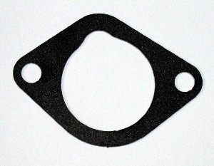
Here's another tip... if you think the intake will be coming off here and there for future projects, spend $12.00 on foam coated aluminum intake manifold gaskets. They are reusable, unlike the factory paper gaskets, so they will eventually save you a few bucks, not to mention time spent cleaning the head or intake surfaces when the paper gaskets stick and tear.
http://www.lindseyracing.com/LR/Pors...63-05-FCA.html
http://www.lindseyracing.com/LR/Pors...63-05-FCA.html
10-29-2013, 12:49 AM
#15
Here's the best pictures I have of the brake booster line. In the first one, you can follow it's path, and see how it goes under the cloth and plugs in.

And it's final set up with manifold installed. The brake booster line runs under the manifold and connects to the middle port on the intake manifold.


And it's final set up with manifold installed. The brake booster line runs under the manifold and connects to the middle port on the intake manifold.
