
KLR.xdf Q's
 12-29-2009, 07:23 PM
#1
Inventor
Rennlist Member
Rennlist Member
Thread Starter
I'm partially disassembling the code, and making a TunerPro 5.0 .XDF file for the KLR. I have done some work on the '85-'86 928 EZF ignition brain, which is similar to the KLR, but I'm a boost noob, so I'm not sure how to scale, label, or make conversions to all the maps I've found. Any info or help would be much appreciated!
My goal is to use the KLR plus other stock 951 parts to eventually control a low boost, mid-turbo, on my '85 928 5-speed.
Notes:
- There are not that many maps, and there is a lot of empty code space
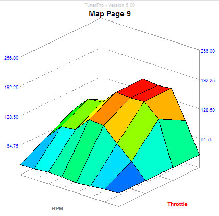
- Maps 9, B, and C are the most interesting
Updates:
- 01.01.10, new map, WOT output, TPS threshold by RPM (stock, all 65%)
right-click, save as...
KLR_XDF.zip 01.01.10
KLR_bins.zip
TunerPro 5.0 beta download page
KLRDataSheets.zip - all chip datasheets
Page 9:
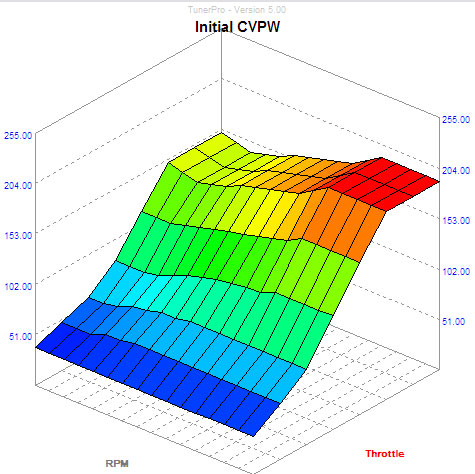
Page B, cycling valve initial pulsewidth
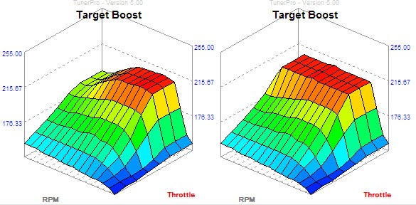
Page C, target boost '87 vs. '89
My goal is to use the KLR plus other stock 951 parts to eventually control a low boost, mid-turbo, on my '85 928 5-speed.
Notes:
- There are not that many maps, and there is a lot of empty code space
- Maps 9, B, and C are the most interesting
Updates:
- 01.01.10, new map, WOT output, TPS threshold by RPM (stock, all 65%)
right-click, save as...
KLR_XDF.zip 01.01.10
KLR_bins.zip
TunerPro 5.0 beta download page
KLRDataSheets.zip - all chip datasheets
Page 9:
Page B, cycling valve initial pulsewidth
Page C, target boost '87 vs. '89
Last edited by PorKen; 01-08-2010 at 02:23 PM.
 12-31-2009, 01:17 AM
#2
Inventor
Rennlist Member
Rennlist Member
Thread Starter
Notes:
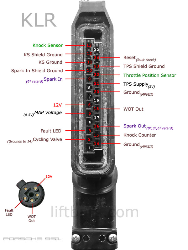
- The DME sends a square wave ignition pulse which has 6� retard to the KLR. The ignition pulse triggers the external interupt routine of the 8039 (=8048) CPU
- The KLR returns a pulse (on the next rev?) which is advanced 3� or 6� over the input pulse, if there is no knocking. The returned signal is a direct output of the processor.
- Pin 1 is described as a diagnostic output, but it is not implemented on the board (missing components).
- Pin 24 is wired to the reset pin of the 8039.
- Pin 9 comes from DME pin 21. (The tachometer is also wired to DME pin 21.)
KLR pinout.
Last edited by PorKen; 01-01-2010 at 09:16 PM.
12-31-2009, 04:04 AM
#3
Addict
Rennlist Member
Rennlist Member
I am curious, why stay with the KLR for a setup such as yours thats so different from its original install? Why not go with something much more modern, like a J&S SafeGuard?
12-31-2009, 04:40 AM
#4
Drifting

Join Date: May 2006
Location: Melbourne
Posts: 3,481
Likes: 0
Received 0 Likes
on
0 Posts
Why ? its free ... why machine a control arm from a billet ?? BECAUSE YOU CAN !!!
I've been hypothesizing about this for ever ..
have you scoped the inputs and outputs to support your theory ?
As an oil field guy i feel things need to be fail safe .
I have an u supported theory that the KLR returns the signal advanced if all is well . if all is not well like repeated knock or insufficient background noise from the sensor it returns the signal Un advanced ..
supporting this theory is that the manual say's the car runs with "decreased performance " (RETARDED) when the KLR is disabled ..
so the KLR intercepts the ignighter trigger signal ?
I would like to try run the KLR with after market management i could possibly run the crank signal directly through it if i was to convert to hall .
don't worry some smarter guys will be along shortly ..
12-31-2009, 06:15 AM
#5
Instructor
Join Date: Feb 2002
Location: Germany
Posts: 201
Likes: 0
Received 0 Likes
on
0 Posts
I'm partially disassembling the code, and making a TunerPro 5.0 .XDF file for the KLR. I have done some work on the '85-'86 928 EZF ignition brain, which is similar to the KLR, but I'm a boost noob, so I'm not sure how to scale, label, or make conversions to all the maps I've found. Any info or help would be much appreciated!
Map B (rpm/throttle) are start values to generate the PWM signal for the CV. Map C are the target boost values. The PWM signal ist corrected by a PID algorithm to reach the target boost.
The PID part of the software is a masterpiece. It is lightning fast so you normally don't have to care about map B.
To adapt the KLR it is important to understand how it works. It is not a stand-alone system that runs by itself. It does not loop. It is a kind of one-way code. It needs a trigger signal that causes a reset to the cpu before it can control the next ignition timing. The time between trigger and ignition signal is used to calc the rpm parameter. All the other work like boost control, knock detecting, etc is done in the time until the next reset.
Anyway - the code is simple and small and should easily be disassembled on a rainy weekend.
Last edited by Transaxle; 12-31-2009 at 06:40 AM.
12-31-2009, 11:51 AM
#7
Addict
Rennlist Member
Rennlist Member
Why ? its free ... why machine a control arm from a billet ?? BECAUSE YOU CAN !!!
I've been hypothesizing about this for ever ..
have you scoped the inputs and outputs to support your theory ?
As an oil field guy i feel things need to be fail safe .
I have an u supported theory that the KLR returns the signal advanced if all is well . if all is not well like repeated knock or insufficient background noise from the sensor it returns the signal Un advanced ..
supporting this theory is that the manual say's the car runs with "decreased performance " (RETARDED) when the KLR is disabled ..
so the KLR intercepts the ignighter trigger signal ?
I would like to try run the KLR with after market management i could possibly run the crank signal directly through it if i was to convert to hall .
don't worry some smarter guys will be along shortly ..
I've been hypothesizing about this for ever ..
have you scoped the inputs and outputs to support your theory ?
As an oil field guy i feel things need to be fail safe .
I have an u supported theory that the KLR returns the signal advanced if all is well . if all is not well like repeated knock or insufficient background noise from the sensor it returns the signal Un advanced ..
supporting this theory is that the manual say's the car runs with "decreased performance " (RETARDED) when the KLR is disabled ..
so the KLR intercepts the ignighter trigger signal ?
I would like to try run the KLR with after market management i could possibly run the crank signal directly through it if i was to convert to hall .
don't worry some smarter guys will be along shortly ..
You would need to scope the output from the DME. It has a divider circuit on it that divides the speed pulses down to a lower number than 132. Then perhaps it could be used standalone....
Trending Topics
12-31-2009, 01:13 PM
#8
Instructor
Join Date: Feb 2002
Location: Germany
Posts: 201
Likes: 0
Received 0 Likes
on
0 Posts
The KLR gets the final ignition signal from the DME. If all is well it returns it immeadetly to the DME and from there to the coil. If all is not well it delays the signal and returns it after a defined time that correlates to a multiple of ~3�.
Everything is initiated by the trigger signal that is sent exactly 4 teeth (~11�) before the ignition signal. The time between both signals gives the actual engine speed.
12-31-2009, 02:08 PM
#9
Rennlist Member
Can you jumper pin 16 to pin 9, and bypass the KLR for the ignition signal?
I have been trouble shooting a power loss problem, and would like to ensure that the KLR is not retarding timing.
I have been trouble shooting a power loss problem, and would like to ensure that the KLR is not retarding timing.
12-31-2009, 02:34 PM
#10
Instructor
Join Date: Feb 2002
Location: Germany
Posts: 201
Likes: 0
Received 0 Likes
on
0 Posts
Jep - that works. But the KLR will not build up any boost. If you use a separate boost controller you should do that shortcut.
12-31-2009, 03:16 PM
#11
Rennlist Member
12-31-2009, 04:25 PM
#12
Inventor
Rennlist Member
Rennlist Member
Thread Starter
XDF updated.
Datasheets added.
Pinout updated.
Maps added.
I saw your thread in my previous searches. Very informative! I will probably modify the EZF ignition brain in my 928 S3 (85-86) in a similar manner to make it boost sensitive. (As well as modify to allow it to use a 4K 2732 EPROM like the KLR, versus the stock 2K 2716.)
I had to look up what (PID) meant! Interesting.
The EZF is a dual coil controller, so I probably won't be able to use the retard feature of the KLR. I may not be able to use it at all if I can't figure out a routine to calculate rpm without the reset. At least there is lots of empty space for new programming!
Any idea what the Page 9 map does?
Datasheets added.
Pinout updated.
Maps added.
I went through this some time ago when I replaced the stock pressure sensor.
Map B (rpm/throttle) are start values to generate the PWM signal for the CV. Map C are the target boost values. The PWM signal ist corrected by a PID algorithm to reach the target boost.
The PID part of the software is a masterpiece. It is lightning fast so you normally don't have to care about map B.
To adapt the KLR it is important to understand how it works. It is not a stand-alone system that runs by itself. It does not loop. It is a kind of one-way code. It needs a trigger signal that causes a reset to the cpu before it can control the next ignition timing. The time between trigger and ignition signal is used to calc the rpm parameter. All the other work like boost control, knock detecting, etc is done in the time until the next reset.
Anyway - the code is simple and small and should easily be disassembled on a rainy weekend.
I had to look up what (PID) meant! Interesting.
The EZF is a dual coil controller, so I probably won't be able to use the retard feature of the KLR. I may not be able to use it at all if I can't figure out a routine to calculate rpm without the reset. At least there is lots of empty space for new programming!
Any idea what the Page 9 map does?
Last edited by PorKen; 01-07-2010 at 11:23 PM.