
"86" Turbo Harness Continuity Test
 01-30-2008, 01:11 AM
#1
Three Wheelin'
Thread Starter
First off, sorry for the length of this... here's the situation...I've been trying to figure out a NO start problem for a while now. After a long rebuild that included a few FUN upgrades and cosmedic changes and finally getting to that point of anxiety "will it start"...it didn't. Sounded at first like a fuel issue, that system checked out OK. Checked for spark at the coil/plugs had it, didn't have it??? mmm Checked the DME comp & relay they're good. Posted a couple of threads regarding and recieved some good suggestions...no luck.
Here's how it started. When the engine was out I pulled the harness to install a new LR injector/ knock sensor harness and an LR Stage II MAF. Figured that while it was out I might as well clean up the thing and removed all the brittle 20 yr old plastic sheathing and re-cover it with fire sleeving (pic below). Being VERY careful to make sure every wire went back to its' original connection (cut each wire at varying lengths/each wire is color coded so it was really pretty simple). That comment will come back to haunt me. Anyway , since I pulled it back out to check ALL the connections for integrity, I performed a complete continuity test on every PIN, PORT & PLUG! One plus in this, is that I had a second harness to compare...they both checked out the same!
Below are my findings of this test. Again this was an 86 Turbo, I don't know if they're the same throughout the years. I hope some of you can use this info. If there are any red flags here...please let me know. I'm about to re-install this harness, hopefully for the last time.
DME
1 grn 14 pin #1
2 wht/blk TPS #6
3 wht/wht Test plug"B" KLR #18
4 rd/blk 14 pin #7
5 Lg. brn 4 pin DME #4, Alt. switch#1, Codes #2, DME #28, KLR #20, Mark sensor #1, NTC water plug #1, Test plug "C", TPS #4
6 yel/rd vain #2(LR MAF) MAF #3
7 gr/rd MAF #5
8 sm.brn Speed sensor #1
9 blu/grn Air meter power, spliced into for 12v power for MAF
10 brn/wht Codes plug #1
11 wht/grn 4 pin plug DME #1
12 yel/blk Test plug "A"
13 yellow NTC water #2
14 Lg. blu 3 & 4 inj #1 (LR) - stock = grey wire
15 Lg. rd 1 & 2 inj #1 (LR) - stock = grey/blk
16 Lg. brn/yel KLR #14, DME #17 & 19, Lg. grnd, O2 sensor
17 sm.brn/yel Same as above (change DME #16)
18 rd/yel 14 pin #3, DME #35
19 Lg.brn/yel Same as 16 & 17
20 blk/wht 14 pin #5
21 grn/blk 4 pin plug DME #1, 12 pin #3, KLR #9
22 Lg. grn Vain#1 (LR MAF) stock = Air meter #1
23 sm. grn Speed sensor #1
24 green O2 sensor
25 brown Mark sensor #3
26 white Mark sensor #2
27 white Speed sensor #2
28 brown Note - DME #5
29 rd/gry 14 pin plug #13
30 brn/blu Alt switch #2
31 blk/grn KLR #24
32 blk/blu KLR #16
33 blk/wht Idle stab #3
34 rd/blk Idle stab #1
35 rd/yel 14 pin plug #3, MAF #2, DME #18
KLR
1 blu/wht 12 pin plug #12
2 blu/rd Cycling valve #1
3 grn/grn 12 pin plug #11, Test plug "LED"
4 blank
5 rd/wht 4 pin plug DME #3
6 blk/yel 12 pin plug #1, cycling valve, Test plug "UB", 14 pin #2, all inj.idle stab #3
7 blank
8 blank
9 grn/brn-yel 4 pin plug DME, 12 pin #3, DME #21
10 blk Tied in w/#9
11 blk Knock sensor (LR harness) stock = white wire
12 bare Knock sensor ( " " ) stock = blk
13 clear Knock sensor ( " " ) stock = brown
14 brn/yel Lg grnd., DME #16, 17 & 19, O2 sensor
15 blu 12 pin plug #4
16 blk/blu DME #32
17 blank
18 wht/wht DME #3, Test plug "B"
19 blank
20 brn/yel 4 pin plug #2, 12 pin #2, Alt switch #, Codes plug #1, DME #5 & 28, NTC water plug #1, Test plug "C", TPS #4
21 wht/rd TPS #1
22 wht/grn TPS #3
23 wht/blu TPS #2
24 blk/grn DME #31
Other connections
MAF #4 to Vain #2 (LR MAF)
14 pin plug #8 to
14 pin #10 to
14 pin #11 to Turbo water
14 Pin plug #6 to oil sender
14 pin plug #9 to oil sender
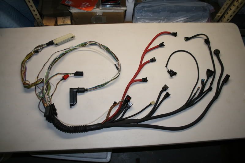
Last edited by Fluidplay; 01-30-2008 at 02:10 AM.
 01-30-2008, 01:53 AM
#2
Drifting
I think you need to do the test a differant way. The problem with a continuity test is you are only testing continuity, meaning, automotive wire is multi-strand and if out of all the strands of wire only 1 strand needs to be connected for it to have continuity. It will not carry any load but it will pass your test.
You said you have no spark at the plugs. Do you have spark at the coil? Did you ohm test the coil? Do you have injector pulse? When you crank the car is the DME pulling the green wire pin 1 at the DME to ground? Does the car have a factory or aftermarket alarm?
I just went through this with a customers car. It had not run since last June or so. It had a bad engine harness due to a previous shops mistake. You also need to measure voltage drop across the ground at the chassis. I have had a ton of these cars have excessive voltage drop and create all kinds of problems. I posted this somewhere else and received close to 10 PM's from people asking how to measure this. Those that replied had too much drop.
01-30-2008, 11:04 AM
#3
Three Wheelin'
Thread Starter
Chris - we had spark at both coil & plugs. The injectors had a pulse. No alarm system. How do you measure for these kinds of voltage drops? Thanks for your input.
01-30-2008, 04:30 PM
#4
Race Car
Join Date: Sep 2005
Location: TEXAS
Posts: 4,247
Likes: 0
Received 0 Likes
on
0 Posts
And thank you for taking the time out to post this. It may not be a complete fix it reference, but it is a great wiring starting point.
Now go install it in the car. A few continuity points are added. At leas for me. I hate wiring.
01-30-2008, 10:41 PM
#5
Drifting
Everyone has heard about cleaning grounds but how do you know what you just did made any differance to the car? I had an 87 951 in the shop that had excessive voltage drop so I cleaned the grounds. A few days later while tuning the low rpm low load of a piggyback the coolant temp guage started to go up, the voltage down and the oil pressure down. I put a battery charger on it and it made no differance. So I measured the voltage drop across the ground and found it to be in excess of 1.2 volts. Now I know that I had cleaned the grounds and I know that they were acceptable, so what happened?
After a few more measurements I found that the negative cable was bad INSIDE the negative lug at the battery. I had less than 50mv from neg post to cable end but less than 1/2" onto the cable it went over 1.2 volts. So I hooked up a jumper cable from the battery to the engine and got a nice arc when making the connection. All the guages came back and the idle noticably changed.
I replaced the cables with a new set and now have less than 100mv from neg post to cam housing. The battery guage reads almost 14 volts when running. But the car would not idle. It would try to idle then start to die, the engine would flare and it would try to idle and then start to die. I looked at the AFR guage and after it would flare the guage would start climbing to 20:1 and almost die, flare (12:1) and repeat. With the bad cable it ran at 14.5 steady. The ground was so bad the DME could not control the injectors and shut them all the way off.
So how do you measure this on your car? It is quite simple actually. All you need is a volt meter. To measure the ground voltage drop you will attach the positive lead to the battery negative post. The negative lead to the engine. Set the scale to a low voltage scale like 2 volts. Anything more than 150 mv is a problem. You can do the same thing to the positive side by reversing the leads and attaching the positive cable at the battery connection on the starter first then go to the battery terminal on the alt. You can test any circuit like this. It is a usefull test unlike continuity. Continuity tells you that there is a connection but not the quality of it. Like I said before if you have a length of wire that has 100 strands and all of them are cut with the exception of 1 you will have continuity. Does that make the wire good? Will it carry amperage and voltage? Will the consumer on the other end function? What if it was an injector? You can see where I am going here.
The other requirement in doing a voltage drop test is the circuit has to be active. If you are testing battery cables the hardest thing they have to do is supply enough amps to start the engine. So do the test while cranking the engine. If you are testing the stop light circuit then measure voltage drop while the lights are on.
Have fun.
