When you click on links to various merchants on this site and make a purchase, this can result in this site earning a commission. Affiliate programs and affiliations include, but are not limited to, the eBay Partner Network.
60-2 just appeared to be universally acceptable, however any output pattern is just a small matter of firmware tweaks. BTW pretty sure the pattern shown is not what the output from a hall sensor would look like. it's closer to what a VR sensor does.depending on the profile of the blank tooth portion of the wheel.
FYI - The pattern you've shown is indeed what a hall sensor's output would look like, not a VR. Pretty sure all commonly available Hall sensors have the signal processing inside them to convert the output signal to a digital one, meaning they will look like what you have pictured. So when you're setting up your Haltech I think you'll want to set your trigger as Hall sensor, with the pull up resistor turned off probably.
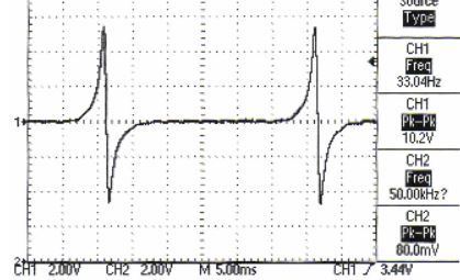
A VR sensor signal will look like this:
Where the ECU will count a trigger event when the voltage crosses the zero point as the tooth leaves the reluctor.
Since the teeth IN vs. OUT align every 12 teeth, then they are out of sync the rest of the time. You will be feeding the ECU inaccurate crank positions. Not a show stopper, there are ways to can get around it.
I went with a 12-1 output pattern. It'll be more accurate and most aftermarket ECUs support it.
The details will take most of your time. Handling possible faults (ex: missing a crank tooth....)
A fun project for sure.
Originally Posted by outathebox
@fast951 as i mentioned above with the 132 input and the sixty tooth output they actually align 12 times a revolution (30 degrees) - . 11 teetrh*2.72727 = 5 teeth *6 degrees. it also aligns every 1/4rev (33/15 teeth) and every 1/6 rev. (22/10 teeth)
what trigger pattern would you have chosen and why?
60-2 just appeared to be universally acceptable, however any output pattern is just a small matter of firmware tweaks. BTW pretty sure the pattern shown is not what the output from a hall sensor would look like. it's closer to what a VR sensor does.depending on the profile of the blank tooth portion of the wheel.
You are spot on about testing that's where the 90-10 rule rears it's ugly head. I plan to have the firmware do some internal consistency checks and aesssment of incoming signal quality. and there is always the trusty mixed signal scope with deep memory and the ability to record signals for a very long time. From what i understand the Haltech has "tooth" diagnostics and has a limited degree of forgiveness with tooth tming as poorly mounted hall sensors don't provide the best signal quality.
@fast951 Doesn't matter that they aren't aligned in between the relationship between the two is 100% consistent. The '132" input RPM and Crank angle exactly equals the "60-2' output RPM and crank angle . The ECU is going to calculate crank angle based solely on the 60-2 pattern - 6 degree of crank angle per tooth. Actual position is relative to the blank period and so as long as the blank period for the 2 missing teeth is consistently aligned with TDC there is no issue.....IMO . That being said under very fast accelerartion (1k-7K in a second) there will be a slight lag of a 1/3 of a degree.
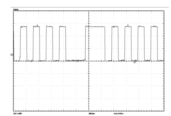
@SirLapsalot sorry i mispoke a bit, the LA shot shows the PROCESSED VR signal after it's been converted from your pic to a digital signal. . What i was trying to say is that i **think** the digital pattern for missing teeth with a hall sensor MIGHT looks like the below shot. from the MasterECU website. There is one missing pulse and one "fat pulse" not two missing pulses. In any evet n the converter can output any required pattern ...not a big deal.
Awesome work!
No direct knowledge of the fuel atomization benefits from sequential operation, but for sure there was a reason the OEMs went to it.
It is pretty easy to take advantage of sequential with the knock control function.
I'm still a long way from having my AEM dialed in, but even at the basic steps, that seems pretty straightforward.
Good luck with your project!
@Nowanker -i'm probably going to use these guy to help me tune "remotely":: https://www.brewedmotorsports.com/pr...-series-2-ecu/ NO affliation, but i've bought stuff from them and they seem knowledeable HOWEVER YMMV.and there are probaly others out there offering similar services.I bartered for access to an engine dyno for my build , but i believe a lot of their customers are doing "road/track tunning" . My theory is track time is really expensive, if i lose a day of track time (or worse) because of a crappy tune then getting some professional help is money very well spent.
@Nowanker -i'm probably going to use these guy to help me tune "remotely":: https://www.brewedmotorsports.com/pr...-series-2-ecu/ NO affliation, but i've bought stuff from them and they seem knowledeable HOWEVER YMMV.and there are probaly others out there offering similar services.I bartered for access to an engine dyno for my build , but i believe a lot of their customers are doing "road/track tunning" . My theory is track time is really expensive, if i lose a day of track time (or worse) because of a crappy tune then getting some professional help is money very well spent.
The remote tuning is an interesting concept, and quite helpful for those who don't live anywhere near a good dyno tuning facility. They do publish a good guide of items to pre-check before using their services, because so many "tuning" issues end up being things like vacuum/boost leaks, timing/trigger errors, erroneous sensor readings, bad grounds, etc. You should also make sure your fuel system is up to snuff, as in proper fuel pump and wiring, properly sized supply lines, etc. It seems like you have the capability to do your homework and make sure all of the sensor inputs/outputs are as they should be before generating the datalogs.
@Nowanker -i'm probably going to use these guy to help me tune "remotely":: https://www.brewedmotorsports.com/pr...-series-2-ecu/ NO affliation, but i've bought stuff from them and they seem knowledeable HOWEVER YMMV.and there are probaly others out there offering similar services.I bartered for access to an engine dyno for my build , but i believe a lot of their customers are doing "road/track tunning" . My theory is track time is really expensive, if i lose a day of track time (or worse) because of a crappy tune then getting some professional help is money very well spent.
Dyno services are sparse up here, but we do have a super nice mobile operator, "Dyno2U.com".
He wasn't too familiar with the Infinity box, so I did most of the tuning.myself. Stressful as hell, but pretty straightforward.
Low boost maps are good but still working on 12psi+. It's not too tough at the track. I still get the sessions, just way short on HP (for now!).
Damn, I wish I had a dyno.


 02-06-2022, 12:45 PM

 . That being said under very fast accelerartion (1k-7K in a second) there will be a slight lag of a 1/3 of a degree.