When you click on links to various merchants on this site and make a purchase, this can result in this site earning a commission. Affiliate programs and affiliations include, but are not limited to, the eBay Partner Network.
I'll save you the suspense: once the crossmember is freed up and lowered--in my case, I removed the steering rack bolts and pulled the crossmember right out--you smile and wonder wow this is easy. Then as you go to put the crossmember back, suddenly the bolt holes are nowhere near where they should be.
Lining those bolts up is far more hassle than lining up that transmission you just installed. At least that was my experience. You'll note that the crossmember bolt you're pulling out will likely have a cut thread at its tip, making it easier to start when not exactly lined up straight.
If you had nice long bolts to sub in--long enough to lower the crossmember and comfortably work on the mounts--it would keep everything lined up and you'd just push the CM back up and sub one bolt at a time. In theory at least
Should you find suitable bolts (or a threaded rod that you could cut and make nice on the ends) please post! With cheap-o motor mounts already buzzing more than I like, I'll probably be doing this again in the near future so I might as well prepare now
Thanks for the spoiler, Dan. I'll definitely take your advice. I guess without the crossmember installed the body probably droops. Great advice.
I need
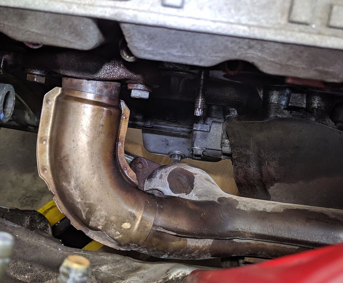
Now that I've got the back of the car done for now, it's time to return to the engine bay. My main goal will be engine mount replacement, but since I need to fix some exhaust leaks, I decided to take the manifolds off now, which will give me better access to the mounts. After taking off the heater hard tube and fuel lines to get access to the flanges, I discover that 5 our of 8 fasteners are not studs, but bolts. Most look like the cheap stuff from the hardware store. Maybe they yielded from the heat, perhaps explaining some of the exhaust flange blowby I noticed (see photo of gaskets below)?
I have a question, though. If the studs need to be removed to get the manifolds out anyway, why on earth uses studs in the first place? A bolt would make more sense to me. Take the bolt out and, voila!, the stud is not there. Can anyone explain the rationale for using studs instead of bolts here? If not, I think I may have to go with bolts. By the way, I was able to get the manifolds off without removing two of the three studs.
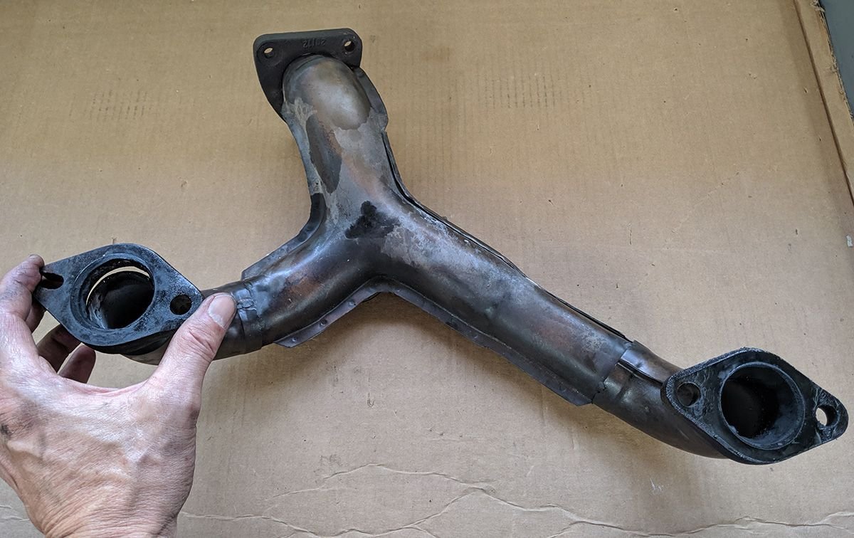
Upon removing the 1+4 manifold, I found an obvious exhaust leak -- the weld was cracked. Upon close inspection, it appears that the weld is not factory-clean. Looks like a home repair gone bad. Not as bad as my welds, mind you, but certainly not top-notch quality. I will repair this weld unless anyone out there has any better ideas.
#1 & #4 manifold; the #4 flange was cracked.
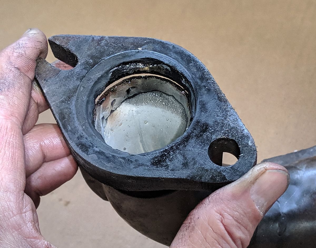
Close-up showing the poor quality of the weld. Looks like a prior repair.
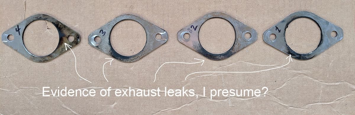
And a final photo showing the source (I suspect) of four other exhaust leaks. I have copper gaskets from Lindsey Racing. I'm assuming these will be better than the ones I'm taking out, again assuming that I get the right clamping force on the flanges using the studs/bolts?
This side of the manifold gaskets showed evidence of blow-by, I think. The other side has some composite material with a stainless ring around the port.
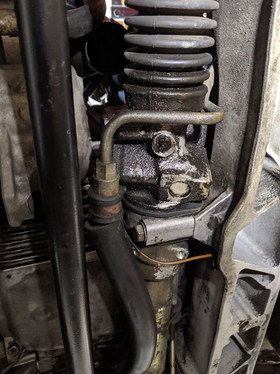
In order to get better access to the engine mounts, I removed the front anti-roll bar. I was down there staring at the rack, daring the one big drop of power steering fluid to drip into my eye, and I thought "why can't I fix these two leaks on either side of the rack?" I had read that it's a very difficult job. Does anyone out there know of someone who rebuilds power steering racks? I'd like to send this one off to get fixed while I've got the car up on stands for a while longer.
Both sides of my rack look like this. It's made more frustrating by the fact that the PS pump that I rebuilt looks pristine.
Zims Autotechnik does a great job on power steering racks. I replaced my entire power steering system 5 years ago and used one of their racks in the process. Also, they recommended that I use power steering fluid instead of Dexron, which I did and it has worked great so far.
If you can do what you just did, then u can rebuild the rack yourself. I rebuilt mine myself and it works great. Take your time and follow the instructions and it will turn out great.
I did did mine after reading about all of the reman racks failing. I experienced two reman rack failures myself and said to heck with it I will try it myself.
Thanks for all your advice, guys, but I splurged and bought a rebuilt rack from Emanuel Istudor at 944Store.com. My project this week was replacing the engine mounts. Thanks to Dan Martinic for the suggestion on getting longer bolts so you can drop the crossmember down further. This was a big help. I bought a pack of five M12x1.5-100 bolts from McMaster-Carr. After removing each crossmember bolt, I threaded the longer bolt up into the hole (with the 5 mm thick washers). Then, per Clark's Garage, after removing the engine mount bolts top and bottom, I used my floor jack to raise the engine. The crossmember drops down a bit, but it's constrained from moving too far due to the steering rack and suspension still being attached. I was then able to use a pry bar to lower the crossmember enough to remove the mounts. Once I figured out how to remove it, putting the new ones in were a bit easier despite the increased height of the mounts. I just had to pry the crossmember down a bit futher.
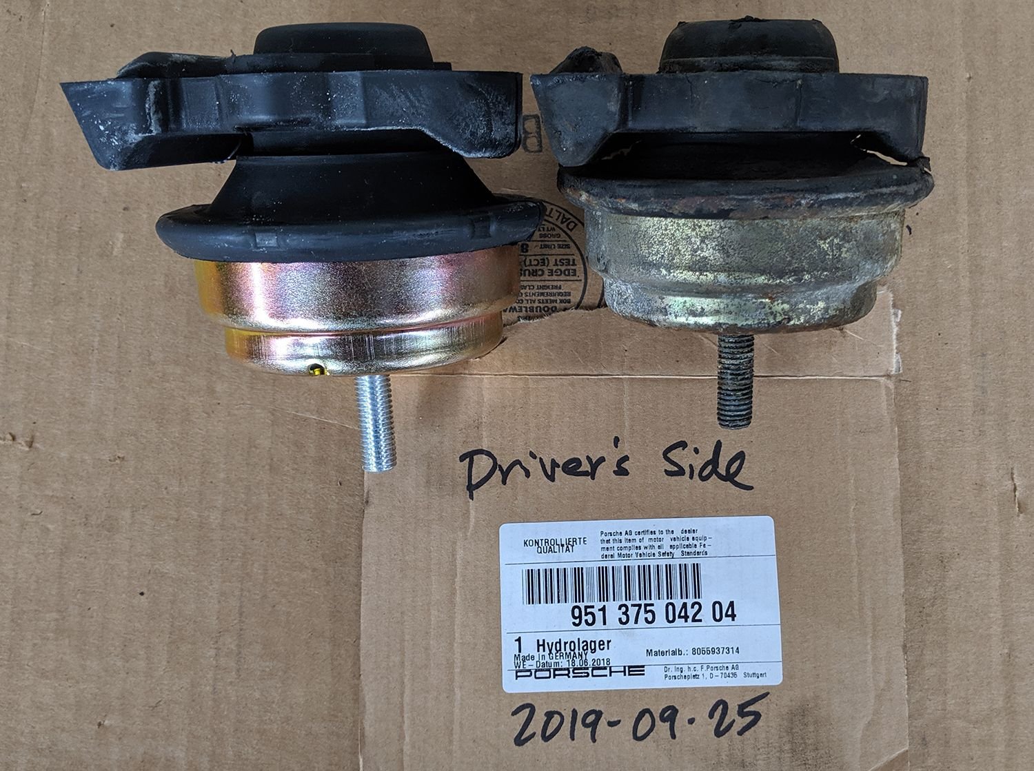
Once I pulled out the mounts and compared them to the new ones, I am looking forward even more to the day I can drive the car and feel the difference they make! There will actually be some rubber cushion between the engine and frame!
Driver's Side mounts showing the difference in height between new and old
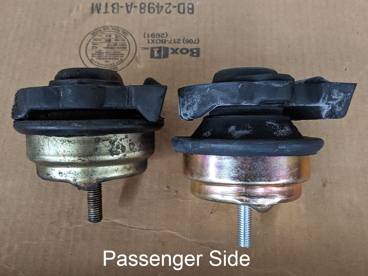
Old vs. New engine mounts on the passenger side.
After getting the mounts in place, I replaced the longer crossmember bolts with the regular ones while the engine was still being lifted by the jack. After securing the crossmember, I lowered the engine onto the mounts. The passenger side dropped right into place, but I had to pry the driver's side a bit while my brother lowered the engine down onto it. Next week I'll put all the bolts in and torque them down properly. After that I have the following projects: install new steering rack, finish the vacuum tube replacements, install the air-fuel ratio gauge, and reinstall the exhaust.
On Monday night, I reinstalled the sensor bracket on top of the flywheel. I set the height with the tool from Dave Gundersen, then installed the sensor toward the front with the factory spacer. Rotated the crank by hand and heard no ticking noises. Then I installed the rear sensor where I had Dave's tool. Turned the crank again and the flywheel scraped the sensor! I know Dave's tool is slightly longer than the sensor to set the height, so the only thing I can think of is that I didn't have his tool seated all the way down on the sensor. I installed the factory spacer under that sensor which eliminated the scraping. I just hope that the sensors are close enough to the triggers to fire them off.
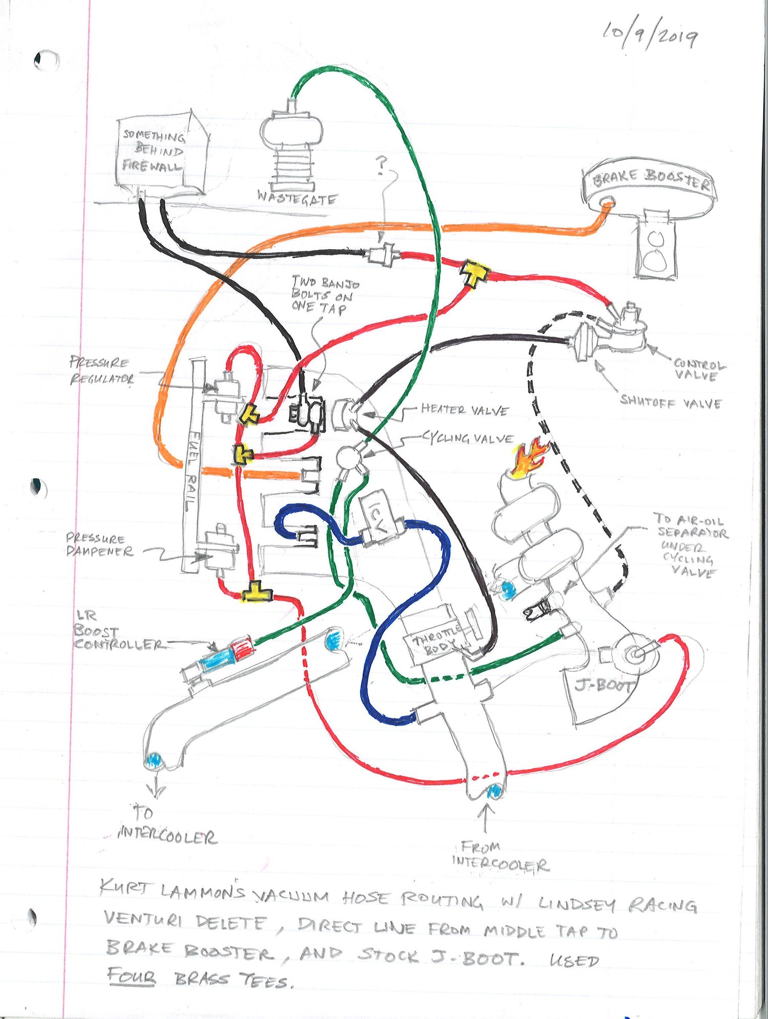
Tonight I finished up the venturi delete kit and vacuum hose routing on top of the engine. I wanted to make sure I didn't have to split the hose going to the brake booster like stock. I have a really hard brake pedal and I suspect that it was mainly due to all the vacuum leaks I had, but by mainlining a tube from the middle tap right to the booster should eliminate any possibility of leaks along the way.
I used the diagrams that Lindsey Racing provides, but it was a bit confusing for me, so I make my own adaptation of their diagram. Mine shows the venturi delete using the stock J-boot. I had to use four brass tees because I only have a single tap on the rearmost vacuum port with two banjo bolts on it. Maybe this diagram and photo will help somebody out there.
Vacuum map showing venturi delete and stock J-boot
I had to use four brass tees Vacuum map showing venturi delete and stock J-boot
Perhaps a bit late.. but if you look up Laust Pederson, you could PM him and ask if has any of these vacuum manifolds left:
And.. where is your KLR vac line? It should be a clear line going from one of the banjo bolts into the car... unless it's one of the lines you've marked already (black going into "something" behind firewall lol)
Hi Dan, thanks for the tip on the vacuum port mod; I think I've got it set up now, but if I have problems I'll contact him. Regarding the clear line, yes, it's there and looks to be in good shape. Still going from the banjo bolt to "something behind the firewall". What does KLR stand for, by the way? Seems like the vacuum lines in the worst shape were the ones between the intake and the turbo; I replaced everything in there.
KLR? Hmm.. never looked it up. Since one of its functions is to monitor and adjust for knock, I guess the K could be something like that.
That clear line travels down to the passenger footwell into the KLR--the second smaller box next to the DME; you might want to check the connection there to ensure it's tight (probably ok but there's a chance that the piece it slips onto has loosened as it threads into the unit)
On Monday night, I reinstalled the sensor bracket on top of the flywheel. I set the height with the tool from Dave Gundersen, then installed the sensor toward the front with the factory spacer. Rotated the crank by hand and heard no ticking noises. Then I installed the rear sensor where I had Dave's tool. Turned the crank again and the flywheel scraped the sensor! I know Dave's tool is slightly longer than the sensor to set the height, so the only thing I can think of is that I didn't have his tool seated all the way down on the sensor. I installed the factory spacer under that sensor which eliminated the scraping. I just hope that the sensors are close enough to the triggers to fire them off.
Tonight I finished up the venturi delete kit and vacuum hose routing on top of the engine. I wanted to make sure I didn't have to split the hose going to the brake booster like stock. I have a really hard brake pedal and I suspect that it was mainly due to all the vacuum leaks I had, but by mainlining a tube from the middle tap right to the booster should eliminate any possibility of leaks along the way.
I used the diagrams that Lindsey Racing provides, but it was a bit confusing for me, so I make my own adaptation of their diagram. Mine shows the venturi delete using the stock J-boot. I had to use four brass tees because I only have a single tap on the rearmost vacuum port with two banjo bolts on it. Maybe this diagram and photo will help somebody out there.
Vacuum map showing venturi delete and stock J-boot
It's been a while since my last post, not because I haven't been working on the car, but rather because it's been taking me down different forks in the road as I come across new problems. Then of course, once another part comes off, you think "what else should I do while I'm in here?", thus leading to another fork in the road.
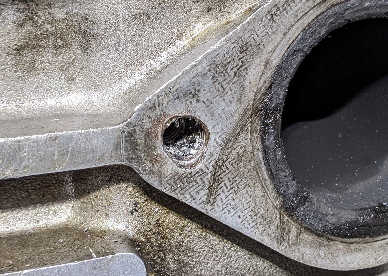
After getting the clutch and engine mounts done, after about 7 months up on jack stands, I was determined to get it back on the road. Upon installation of the exhaust manifolds, I discovered that two of the threaded holes for the exhaust manifold studs were stripped out. That explains the use of the bolts that the previous owner's mechanic must have cross-threaded in there. I realized there was no way for me to Heli-Coil the offending holes without removing the head. So here goes...
Cross-threaded exhaust manifold stud hole
Removing the cam tower wasn't as big a deal as I'd feared it would be. I was able to remove the plastic belt covers without taking off the coolant plumbing or fans without too much trouble. I just loosened the tension on the timing belt and peeled the belt off the cam. I didn't even have to disturb the balance shaft belts. Once the cam tower was off, the head came off pretty easy except that it took the force of Thor and a breaker bar to break the torque on the head nuts. One of the two allen bolts in the forward rectangular coolant passage snapped off; gotta get that out. I called to a couple of machine shops about doing the Heli-Coils and head work, but decided to get a freshly-rebuilt head from Emanuel Istudor of 944store.com instead for $450.
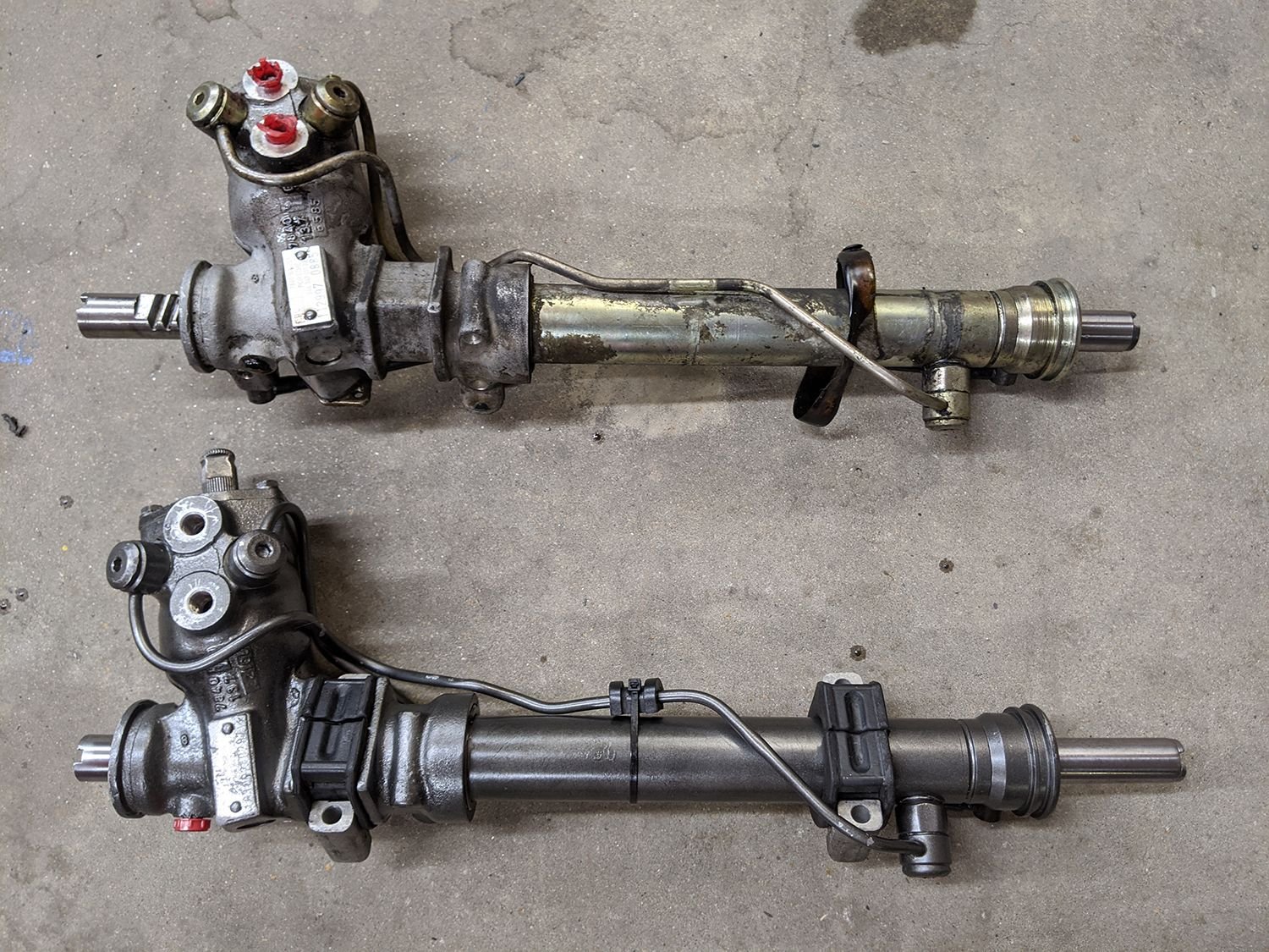
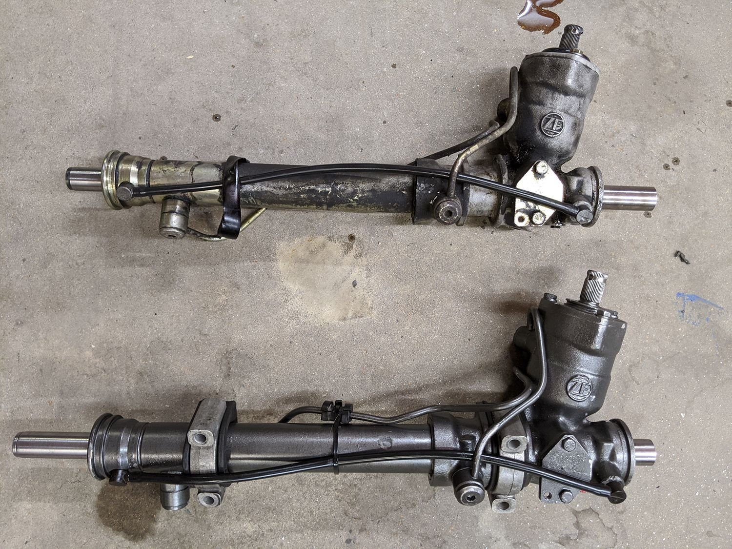
While the head was off, it was a good time for me to get the old leaky steering rack off and exchange it for the rebuilt one I bought from Emanuel a few months ago. I got it off last night following the instructions on Clark's Garage. My only modification was to grind out the peened-over anti-rotation feature where the tie rod screws into the ends of the rack. I used a small cutter bit and removed the upset metal. Once I broke the torque on these, they unthreaded very easily. Then I swapped over the hardware from the old rack to the new one. Below are a couple pictures of the back and front of the rack. The low pressure line goes into the top hole, and the high pressure line goes to the lower hole.
Low pressure to top hole, high pressure to bottom. Use 17 mm wrench to remove the banjo bolts -- an offset box wrench was essential as I couldn't get a rachet in there. Already swapped over the clamps to the new rack.
Now that the rack and head are off, I have very nice access to the oil filter console. I had bought an aftermarket oil cooler from Lindsey Racing a couple years ago, but lack of access to this area put me off of installing it. Now's the time! I tried to get a crescent wrench onto the nut on the top line, but the wrench is too bulky and interferes with surrounding hardware. So I bought a 32 mm line wrench from Pegasus Racing last night online. I'll check in again later with info on the oil cooler swap.
So, the plan from here is:
1. Install Lindsey Racing aftermarket oil cooler
2. Reinstall steering rack with new tie rod ends
3. Remove broken-off bolt in the block (the one allen bolt that broke off which clamps down the rectangular coolant passage at the front-top of the head.)
4. Install the rebuilt cylinder head; then the cam tower, get the belt on and tensioned.
5. Install the heat shields under the exhaust manifold.
6. Install the exhaust manifolds.
7. Reassemble all of the intake and exhaust stuff
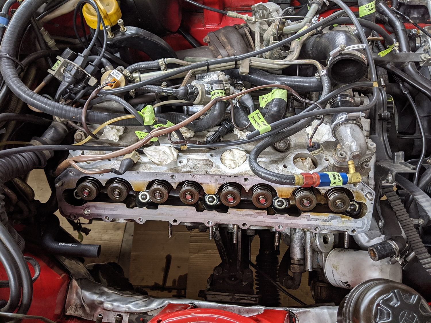
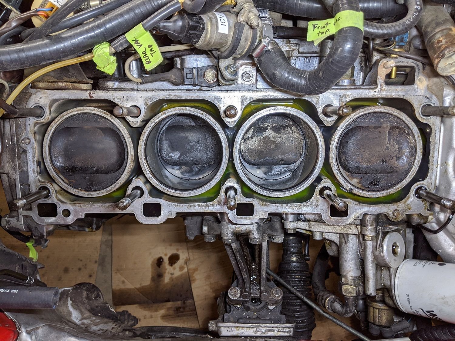
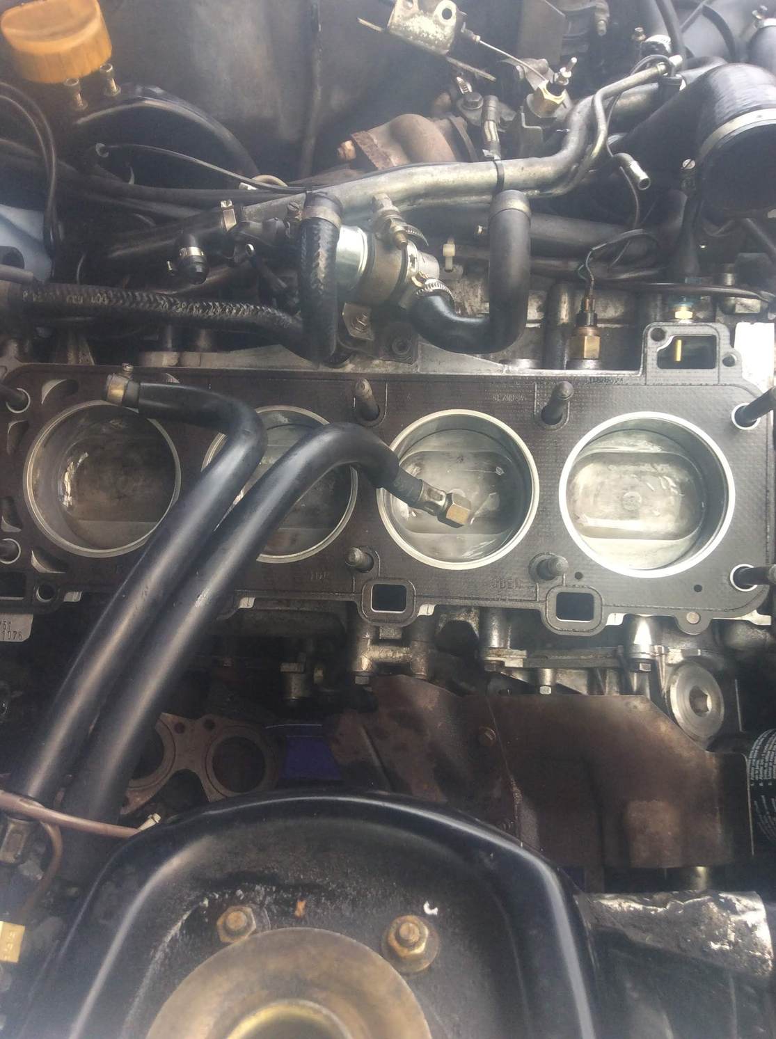
That's all for now. I'll check in after Christmas hopefully with news about an uneventful installation of the LR oil cooler. Oh, and below are a couple of photos of the engine with the cam tower removed and with the head removed for reference for those who are considering the job or are in the middle of it. I hope all these photos are helpful to someone out there.
Photo of head with cam tower removed
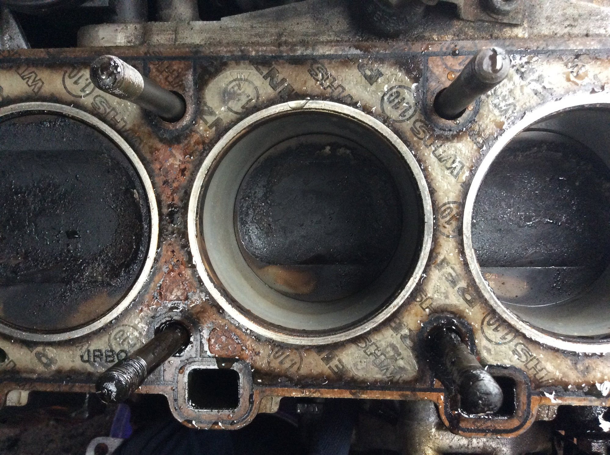
Photo of engine with head removed. The cylinder linings look great, thankfully. I really don't want to take the engine out at this point! I'm hoping to drive the car in 2020.
Nice work! Very inspiring. I'm currently in the middle of some work myself.. taking my time--it's basically outside and freezing--but your story prompts me to increase the pace
I strongly suggest you clean off all that carbon buildup on the pistons. True story: a short while ago, I was failing emissions testing. I changed the cat.. made all kinds of little fixes... still nothing. Then, I decided to change the HG, which of course didn't look obviously bad in itself. But, in the process I cleaned all that crap off the piston tops. Bingo--passed the test with better numbers than I've ever seen in the past ten years
Just spray WD40 on a green Scotchbrite pad and rub away. Afterwards, I vacuumed up any debris before moving anything.
Wow! Thanks for the tip, Dan. I will definitely do that. I'd like it all to be clean when I put the head back on because I hope not to see those pistons again for a long time!

 09-19-2019, 08:44 PM