When you click on links to various merchants on this site and make a purchase, this can result in this site earning a commission. Affiliate programs and affiliations include, but are not limited to, the eBay Partner Network.
Started looking at WB02s. Um... seems you can buy separate sensors and gauges (at $200+ USD EACH) or kits which appear significantly cheaper (ex $250 USD for both gauge and sensor: https://www.aemelectronics.com/produ...uge#buy-direct )
I guess I'm asking what is a good yet relatively inexpensive setup? I'm looking for an analog gauge for a stock-like look. Odd: I can't seem to find a VDO stock-style afr gauge. Don't they make them?
I'm a fan of Zeitronix, but there are lots of them out there. Google wideband gauge and browse the images. There are some pure analog-looking gauges that get close to the VDO look (AEM, MSD, Holly). You really do want a digital read-out though, and logging. That way you can tell if the car is actually dithering around the 14.7 and see exactly what happens to your WOT curve when you make changes. If you just have a needle gauge and no logging, it's like smearing Vaseline on the end of your binoculars. (You can always hide the gauge or use it only when needed for diagnostics.) I think widebands are worthwhile for just about any 951, but if your sole goal right now is to confirm you are getting into closed loop, you could use that scope of yours, or a cheap narrow band gauge, or a DIY-electronics do-hickey, etc., in lieu of a wideband...
I see your point re: gauge type. You're right: I could just hide it and I'd probably prefer that. I actually found one that transmits to the cell phone; maybe that's the best for me.
In the meantime, tell me more how to use my little 'scope to check for closed-loop
Wait--I think I know: hook it up to the O2 sensor and see if it responds to changes in afr such as pulling a vac line or adding propane? Except I can't see how to back-probe that connector. I suppose I could take if from the DME end by back-probing through the (open) harness connector?
Wait--I think I know: hook it up to the O2 sensor and see if it responds to changes in afr such as pulling a vac line or adding propane? Except I can't see how to back-probe that connector. I suppose I could take if from the DME end by back-probing through the (open) harness connector?
Is there an easier way or back-probing trick?
I'd probably tap the signal at the barrel connector under the hood, in the same clip with your favorite speed/ref sensor connectors. As for the scope, drive down the road at various constant speeds (and idle) and make sure the voltage is dithering around 14.7 -- i.e., that it is bouncing back and forth above and below about .45 volts. It won't alternate at a constant rate, but rather somewhat randomly above and below that voltage as the DME adds and subtracts fuel to keep it as close to 14.7 as it can. If it stays well above .45v for more than a few seconds, or spends the great majority of its time above .45v, then it means the DME is leaning it out as much as it can, but can't lean it out enough to keep it where you want it (or the sensor/system is bad). Make sense? The narrow band is nearly a binary sensor, with it's only real information being whether the mixture is richer (above .45v) or leaner (below .45v) than stochiometric (i.e., 14.7 for most pump gas). Pulling vacuum lines and adding propane, etc. might confirm if the closed-loop system is functioning, but it's not a good way to tell if the car is running rich on the road.
"I'd probably tap the signal at the barrel connector..." - this is the part I'm stuck on! How do you tap into that connector without damaging it?
The rest I get. PS.. If I pull the connector and check pin voltage with a digital voltmeter, I get steady .9v at idle. Revving causes some changes then back to .9v.
I realize it's not ideal but... doesn't that pin's voltage indicate what the DME sees? Shouldn't it be around .45v --average--?
If the jumper idea isn't clear, here's a picture I borrowed from a Pelican thread to give you the basic idea...
Originally Posted by Dan Martinic
"I'd probably tap the signal at the barrel connector..." - this is the part I'm stuck on! How do you tap into that connector without damaging it?
The rest I get. PS.. If I pull the connector and check pin voltage with a digital voltmeter, I get steady .9v at idle. Revving causes some changes then back to .9v.
I realize it's not ideal but... doesn't that pin's voltage indicate what the DME sees? Shouldn't it be around .45v --average--?
Most multimeters react too slowly to get a good reading from an O2 sensor, and if you pull the connector apart to test is (which is what I understand you did) then the DME will not have the benefit of the sensor signal and won't be able to make adjustments. Your .9v reading is only of limited value as a result. It suggests the car may be rich at idle when running on base maps, but doesn't help you know if the closed loop system is able to bring it back in line. The reading itself isn't really reliable either with a multimeter since we don't know what it does with such small voltages changing faster than it can sample. That's why I suggested the scope (since you have it) so you can see what's really happening with confidence. To tap at the barrel connector, you can make up three little bridge wires of 2 or 3 inches each and tap into the signal one. Molex .62 female terminals work good enough and are easy to find, or you can get creative with whatever is handy (expanding/smashing other terminals to work for testing, etc.). If that's all too jerry-rigged for your sensibilities, you could also just put an alligator clip on the metal part of the O2 pin where the main connector is soldered into the DME mother board. However you do it, you want the system connected and working to test it though...
Got it! I'll be taking the signal with the connector disconnected but the signal pin hooked up with a jumper. I'm assuming the other two connections don't need to be connected--they are for the heater only then?
This should be easy... except I'll be viewing the scope under the hood, not while driving, which is fine with me as long as I can get enough info, perhaps while raising the rpm a bit to about 2500 or so. I read somewhere that is the speed for testiing.
I'd hook up all three wires. A cold O2 sensor is an inaccurate O2 sensor. Also, I'd take a co-pilot along and drive it on the road, with the scope on your lap. Reving it in the garage puts surprisingly little load on the motor -- barely more than idle really -- at least in terms of the 0-5v sweep of the AFM.
Ok... but how do I get the wires into the passenger compartment from the engine bay? Perhaps laughable, but I don't see how with all the tight seals between engine & hood!
Sure... but it doesn't look like you can squeeze much between the hood and its seals? Maybe through the fender side; I'll check it out. Hopefully the length of the wires won't make a difference...
Ok... but how do I get the wires into the passenger compartment from the engine bay? Perhaps laughable, but I don't see how with all the tight seals between engine & hood!
If you are brave, you can pull out the massive rubber grommet for the DME wiring harness and run the wires through there. That is what I have been doing with the extra sensor and power wires for my VEMS ECU. If the installation becomes permanent, you can cut a slit in one side of the grommet and run the extra wires through there. Then make sure you lube up the grommet with silicone grease or similar to give yourself a fighting chance of getting it back in!
For testing my various Wile E. Coyote projects, I have a long history of running wires out the engine bay at the base of the windshield and into the cabin through a cracked window. Easy-Peasy. The weather-stripping on top of the inner firewall is soft and covers a big gap, so running a wire or two over it and closing the hood fully isn't an issue at all.
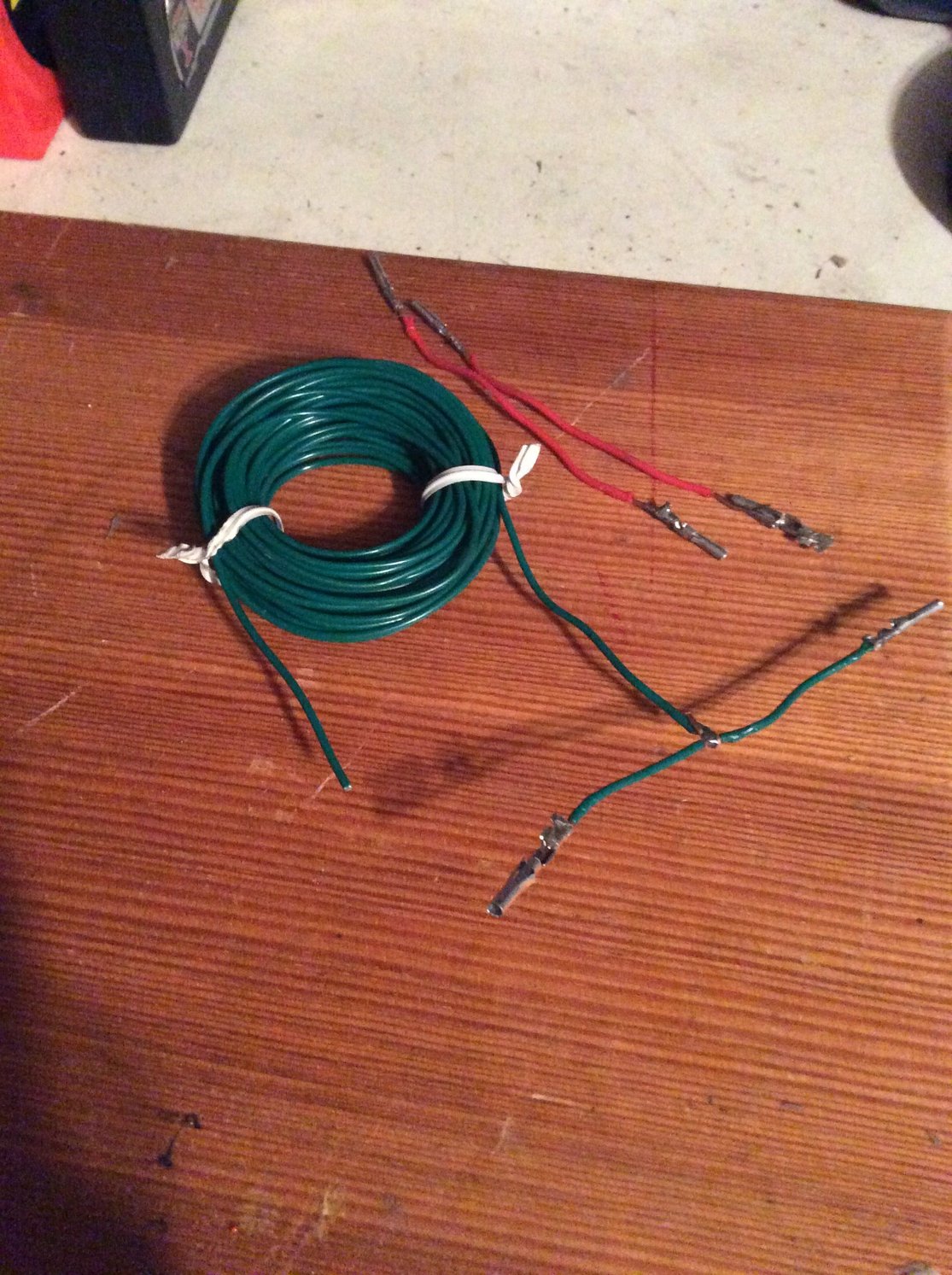
I made my own version of the testing wires. Wish I had the actual pins; the Molex .062 are only good for the holes (using the female .062--took me a while to figure that out). The .062 males are too small. The female doesn't fit on the O2 plug male pin. The next size up .093 are too big.
I mangled a few and ended up with having to use my last one backwards.. don't ask
I suppose the originals are some older metric sizes and not readily available at the local electronics store
I just have to wrap the ends with heat shrink. I would imagine I only have to take the signal off that one pin ie. the one wire I'll run into the passenger area? That is, I won't have to connect the 'scope ground anywhere, correct?
I also made a 9-volt adapter plug for the 'scope.... now to figure out where to place all that so I can view while driving. This is no simple setup..
Looks good enough -- you aren't wiring up a mars rover after all. The scope needs a ground signal to work, but any solid chassis ground should be good enough to see if it's dithering around its closed-loop point. Given the small voltages, slight resistances to ground can throw off the voltage reading a bit, but you aren't really looking to confirm specific voltages, just that it is bouncing above and below something in the neighborhood of .45v.


 12-18-2018, 01:07 PM


 Reving it in the garage puts surprisingly little load on the motor -- barely more than idle really -- at least in terms of the 0-5v sweep of the AFM.