

Testing central warning unit

Thread Starter
Burning Brakes

Joined: May 2016
Posts: 840
Likes: 56
From: Nazareth, PA
All warning lights illuminate on my instrument cluster EXCEPT the coolant level warning. It is not the bulbs, there is no potential when checked with a volt meter. Entire instrument cluster has been rebuilt and cleaned and the circuit foil is in good condition.
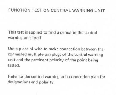
Looking at the manual there is a testing procedure but I do not understand it clearly.
function test.JPG
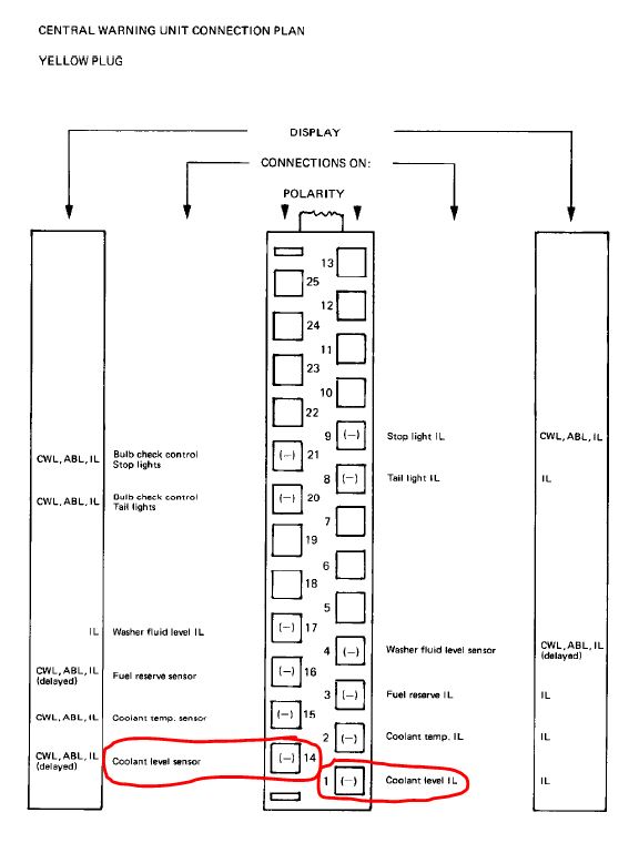
And here is the detail of the yellow plug where the coolant level terminals are found (circled).
yellow.JPG
Do the instructions describe using a three wire jumper between both terminals of the plug (#1 and #14) and negative (chassis)? This should bypass the central warning unit and energize the instrument bulb socket?
Looking at the manual there is a testing procedure but I do not understand it clearly.
function test.JPG
And here is the detail of the yellow plug where the coolant level terminals are found (circled).
yellow.JPG
Do the instructions describe using a three wire jumper between both terminals of the plug (#1 and #14) and negative (chassis)? This should bypass the central warning unit and energize the instrument bulb socket?


Three Wheelin'
Joined: Dec 2002
Posts: 1,825
Likes: 3
From: St Louis, Missouri, USA
I've been looking at this too because I have a bad 83' CWS and would like to just fix the thing rather than buy another 30 year old used CWS box. So here are a couple of things that I try to keep in mind when thinking about this stuff.
First, be aware of the two CWS modes: bulb check mode and the other mode that I call "Running Mode." Bulb check happens with key on but a not yet started engine. Running mode is after you have touched the starter switch position. In running mode all lights are off till a fail happens. Sidenote: sometimes a failing CWS reverts from running mode to bulb check mode while the engine is still running and of course all the lights come on and I promptly fail my yearly Missouri safety inspection.
Info: Looking at the connection plan, the monitored inputs to the CWS have the word sensor in the signal name and the outputs have the abbreviation IL (illumination). Of course there are others like BATT, ignition, starter pulse and ground. Those are things to support the CWS box and control the mode.
Important: 1) The CWS outputs provide a ground to turn on the specific failure light - not a voltage.
2) Transistors such as BC307B is (per digikey) obsolete and are used repeatedly in the CWS.
3) to my knowledge there are no findable schematics of the CWS for MY 83 so you may have to develop one from the cards. This is a mind numbing exercise but if we could just master one sensor/driver circuit, there about 10 others that are exactly like it.
4) If no other way forward is available ... a 3-wire, limp-along hack of the wiring can sometimes be done to make the CWS appear to work (pass bulb check and maintain most of the sensor monitoring but lose the "!" light operation)....Bruce
Thread Starter
Burning Brakes
Joined: May 2016
Posts: 840
Likes: 56
From: Nazareth, PA
Thanks for the input. For clarity I am talking about the instrument cluster bulb test - ignition on but starter not activated. I had a chance to do some tests.
Pin #1 has 4.75v and pin #14 is 0v
I have 9.8v at the circuit foil at one of the bulb contacts.
I grounded pin #14 and still no light.
I will not ground pin #1 because that would be a short circuit.
My problem appears to be on the ground or negative side and should not the positive be 12v?
Pin #1 has 4.75v and pin #14 is 0v
I have 9.8v at the circuit foil at one of the bulb contacts.
I grounded pin #14 and still no light.
I will not ground pin #1 because that would be a short circuit.
My problem appears to be on the ground or negative side and should not the positive be 12v?
Last edited by Majestic Moose; Jun 15, 2017 at 07:23 PM. Reason: corrections
Three Wheelin'
Joined: Dec 2002
Posts: 1,825
Likes: 3
From: St Louis, Missouri, USA
I do have 9.8v at the circuit foil at one of the bulb contacts.
I grounded pin #1 and still no light.
I grounded pin #1 and still no light.
disconnect the CWS (both plugs)
turn on the ignition switch (no engine start)
measure the yellow cable plug, pin 1 for volts - I expect you will see the 9.8 or something close to 12v.
If yes, we know that the volts are coming down from the pod. Use a test lead and ground just that cable's pin 1 and you should see the light (and know the light is good and the CWS wire to the light is good).
If no volts at the disconnected cable yellow plug pin 1, then I would think you have a broken wire between the pod and the cws.
I will not ground pin #14 because that would be a short circuit.
Thread Starter
Burning Brakes
Joined: May 2016
Posts: 840
Likes: 56
From: Nazareth, PA
I have some results!
First a quick correction and I will correct my post above - it is pin #1 that has voltage (at 4.75v, at bulb is 9.8v), pin #14 does not. All conceivable connections in the car are clean and tight.
I confirmed what you said and reviewed the manual and I have a better understanding. Grounding pin #1 is not a short to ground because the bulb is in the circuit and mine lights up by doing this
My conclusion is that there is some defect of my central warning unit and I have ruled out wiring, circuit foil, or bulb problems. I feel that I can reinstall the instrument pod and tackle the central warning in the future.


