Notices
928 Forum 1978-1995
Sponsored by:
Sponsored by: 928 Specialists

More efficient vacuum routing...

Thread Tools
 
Search this Thread
 
Old 11-27-2016 | 06:33 PM
  #1  
drscottsmith's Avatar
drscottsmith
Thread Starter
Three Wheelin'
 
Joined: Jul 2016
Posts: 1,336
Likes: 99
From: Duncan, SC
Default More efficient vacuum routing...

All -

Asking for clarification and efficiency...

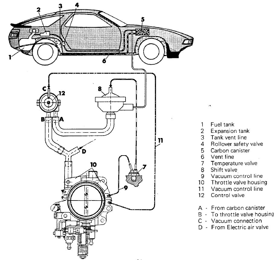
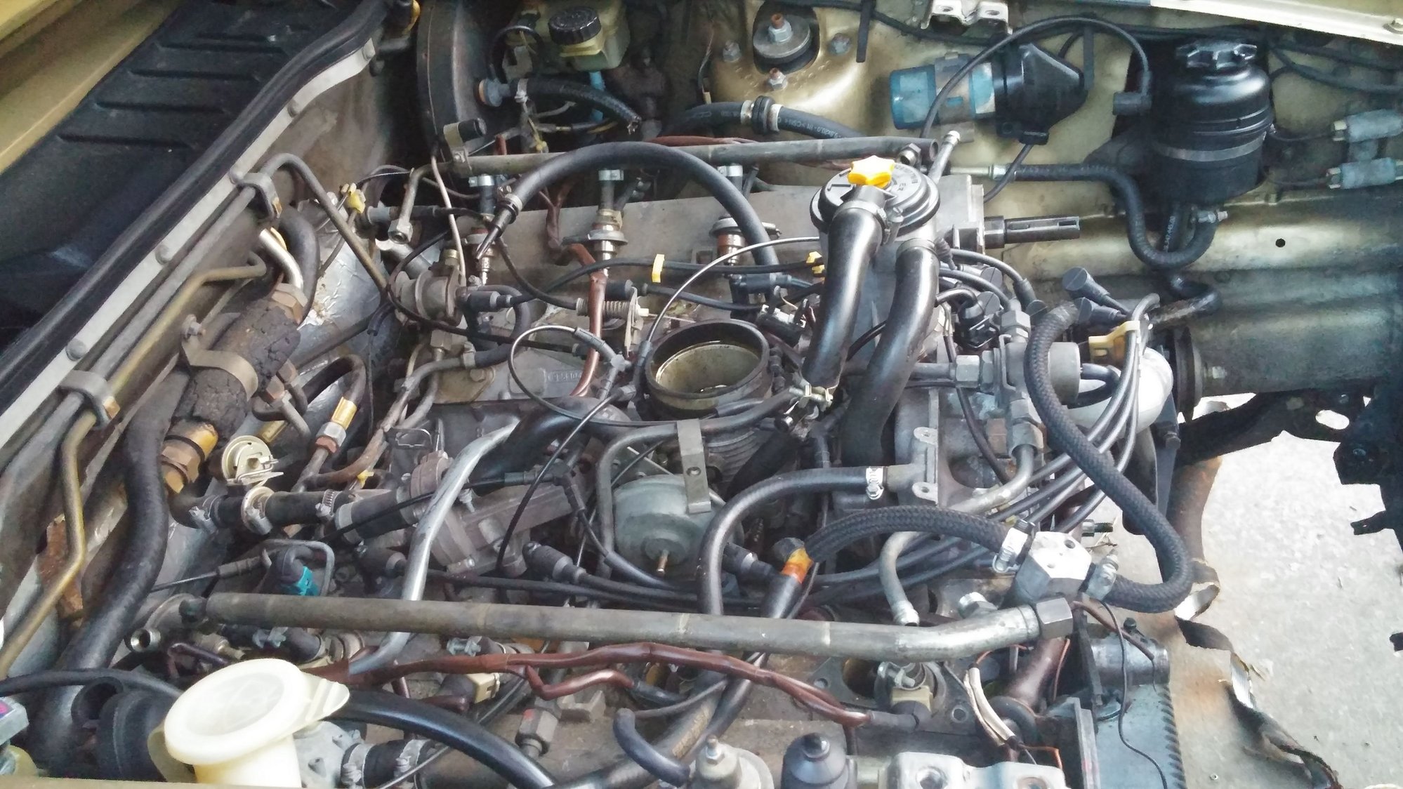
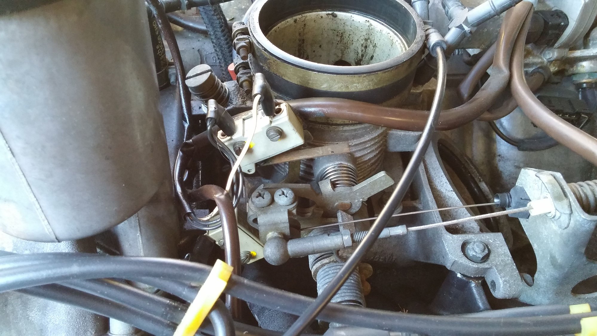
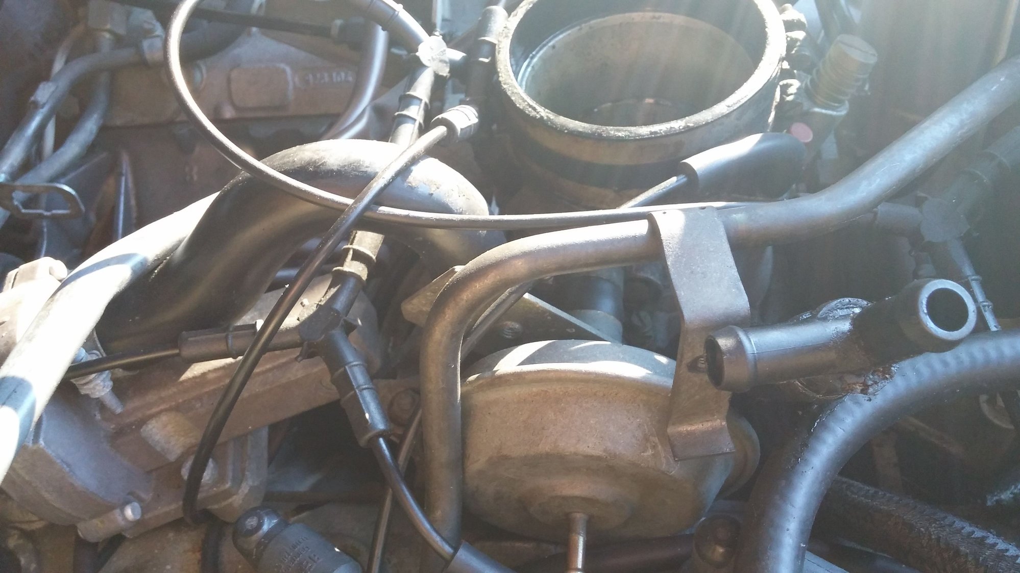
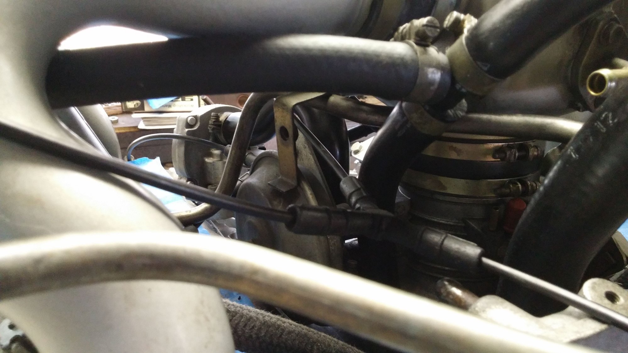
I want to double check the vacuum line routing as I am not sure what I disconnected to replace was correct anyway. Also, the Decel Valve (attached to the side of the throttle) was already removed and I am not putting it back.

So, the attached pdf shows it all...

1-3) I do not know which devices these are and need help identifying. Can I use a combination of Ts and Ys and run all three of these off of one tap on the throttle body?

4) This is connected to the line that feeds the heater valve. It has two vacuum ports. One is currently connected to '3' above. Not sure what its official name is and what it should connect to.

5) Vacuum advance on distributor
6) Fuel damper

---> can 5+6 run off of one tap with a 'Y' off of the throttle body?

8) This is what I have currently set up to feed both fuel pressure regulators on the backside.

I believe I have all of the brake master side connected up good to go.

Thanks all - sorry for the inconvenience of the pdf.

-scott
Attached Images
File Type: pdf
Vac_Lines.pdf (464.9 KB, 293 views)
Old 11-28-2016 | 11:03 AM
  #2  
drscottsmith's Avatar
drscottsmith
Thread Starter
Three Wheelin'
 
Joined: Jul 2016
Posts: 1,336
Likes: 99
From: Duncan, SC
Default A good starting point...

If someone has this diagram for a 1983 US model (L-jetronic) that would be a great starting point.

-scott
Attached Images  
Old 11-28-2016 | 07:41 PM
  #3  
Majestic Moose's Avatar
Majestic Moose
Burning Brakes
 
Joined: May 2016
Posts: 832
Likes: 44
From: Nazareth, PA
Default

#1 & #2 are for the charcoal fuel vapor recovery system.
#3 I have no clue, the PET shows thermo valve.

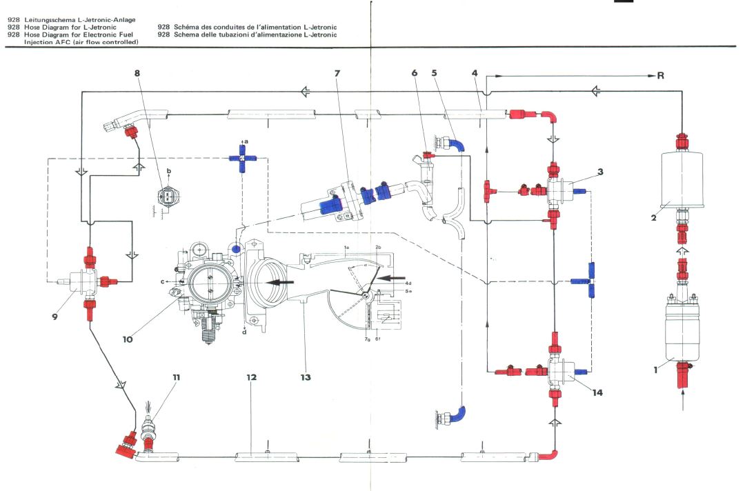
I would reroute all lines as they are shown in the factory manual. I reckon the engineers grouped some things together but used dedicated vacuum lines to other components for a reason.
Following the diagram above is a good start.
Old 11-28-2016 | 09:13 PM
  #4  
drscottsmith's Avatar
drscottsmith
Thread Starter
Three Wheelin'
 
Joined: Jul 2016
Posts: 1,336
Likes: 99
From: Duncan, SC
Default 1983?

Alex -

You dont happen to have that pic for our cars by chance? That one is for a 32v engine and I know there are differences...

-scott
Old 11-28-2016 | 10:39 PM
  #5  
Majestic Moose's Avatar
Majestic Moose
Burning Brakes
 
Joined: May 2016
Posts: 832
Likes: 44
From: Nazareth, PA
Default

Try these:


Name:  CarbonCanister.JPG
Views: 3216
Size:  127.8 KB
Name:  CarbonCanister2.JPG
Views: 2454
Size:  93.0 KB


The short dashed lines are vacuum
Name:  airflow.JPG
Views: 2890
Size:  78.4 KB

Last edited by Majestic Moose; 11-29-2016 at 07:59 AM.
Old 11-29-2016 | 07:16 AM
  #6  
worf928's Avatar
worf928
Addict
Rennlist Member
 
Joined: Oct 2003
Posts: 16,590
Likes: 1,700
From: Gone. On the Open Road
Default

Realize that each vacuum source in the airguide/throttle body has different behavior depending upon the throttle plate position. Route the lines any way you want, but make sure that each vacuum-operated end-point is connected to the correct source.
Old 12-05-2016 | 10:53 AM
  #7  
z driver 88t's Avatar
z driver 88t
Rennlist Member
 
Joined: Feb 2009
Posts: 1,195
Likes: 93
From: Gainesville, FL
Default

Scott,

I did a full photo-documentaion on my 84 L-JET which should have the same routing as yours when I replaced my engine last year.

Here is a link to all 7MB of photos and video, in case that would be useful.
https://www.dropbox.com/s/a8xsvaepaj...hotos.zip?dl=0

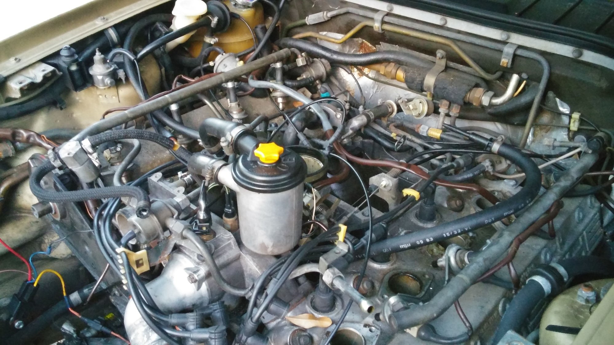
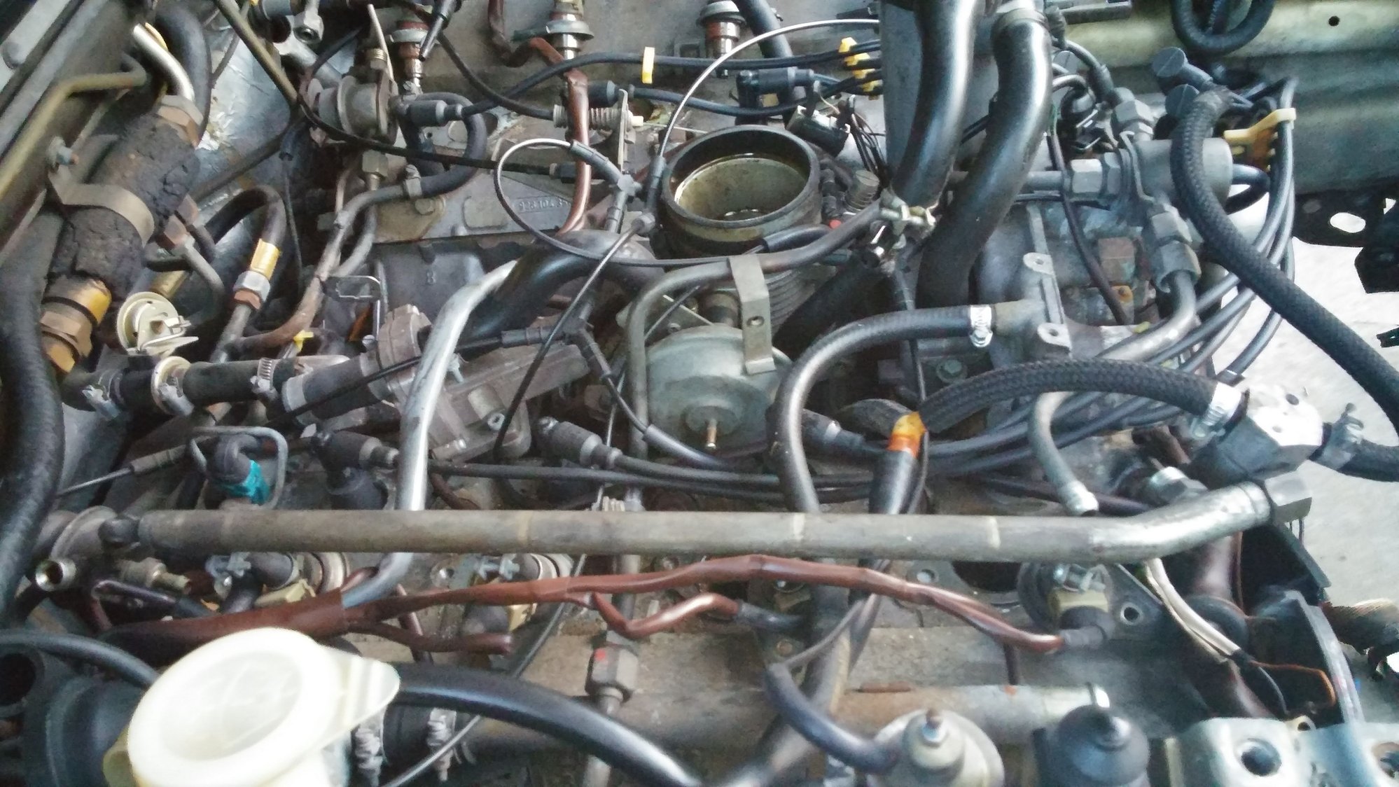
Attached below are most of the photos from the vacuum routing. Good luck. The vacuum routing was one of the things I was most nervous about getting right.


Old 12-05-2016 | 12:09 PM
  #8  
GT6ixer's Avatar
GT6ixer
Race Car
 
Joined: Mar 2016
Posts: 4,144
Likes: 784
From: Gig Harbor. WA
Default

Chris well done. I took a bundle of pics during my refresh but never thought of dictating videos of the routings. Great idea and thanks for the contribution!
Old 12-05-2016 | 12:21 PM
  #9  
drscottsmith's Avatar
drscottsmith
Thread Starter
Three Wheelin'
 
Joined: Jul 2016
Posts: 1,336
Likes: 99
From: Duncan, SC
Default

Thank you for sharing! This is going to be very helpful - I am like you, because of the nature of vacuum in the engine and its variability, I knew there was a "Right Way" to do it!

Thanks again -

-scott
Old 12-06-2016 | 08:26 AM
  #10  
Kiln_Red's Avatar
Kiln_Red
Rennlist Member
 
Joined: Jul 2010
Posts: 1,716
Likes: 364
From: Bowling Green, KY
Default

Off topic.. OP, is that paint code 811? It was only offered for '83 & '84. I have been patiently waiting for a Euro in this color to pop up for sale.

Good luck with your project.
Old 12-06-2016 | 09:26 AM
  #11  
drscottsmith's Avatar
drscottsmith
Thread Starter
Three Wheelin'
 
Joined: Jul 2016
Posts: 1,336
Likes: 99
From: Duncan, SC
Default

Hey Kiln_Red -

I am not sure as the original decal was either removed or painted over. The color is the same in the repaint however (as the underhood, door jambs, etc. are the same).

I have been told that is "Kiln Red" but I am not sure. Rob mentioned that they did not start including paint and interior codes in his records that he uses for options lists until later, so we were not sure.

Is there anywhere else on the car I might could look to verify?

-scott


Quick Reply: More efficient vacuum routing...


All times are GMT -3. The time now is 03:57 PM.