When you click on links to various merchants on this site and make a purchase, this can result in this site earning a commission. Affiliate programs and affiliations include, but are not limited to, the eBay Partner Network.
We had to chase down a leak in Minerva's AC system- I happen to use nitrogen in the lab but the smallest tanks we have are 200 pounders. I stopped by the local Airgas and bought a 20 lb tank, along with some bubble detector juice. Pressurized the system to 100 psi, it leaked down to ~60 in 30 minutes. Significant leak. The bubble juice didn't show us any love (or leaks), unfortunately.
So I picked up a freon leak detector- we partially charged the system with r134a, and in about 2 minutes of sniffing we found the detector would screech next to the un-tight connection at the expansion valve. Tightened that and the system would hold pressure.
So the nitrogen is good to verify that you have a leak, and that you've fixed a leak, but having the sniffer was key to _finding_ the leak...
Hi again everyone and thank you for all your help.
Well, I have power coming in and going out of the freeze switch when the AC button is pushed in, so I think the relay in the AC dash controller is good, but have no power at the low pressure switch as said yesterday. Dwayne's write up states that the next step down the line from the freeze switch is the pressure switch (where I have no power). Also, if I jump power to the pressure switch, the compressor operates, and from his write up it appears the 14 pin connector is between the pressure switch and the compressor, so I'm assuming the 14 pin is fine. I opened it up yesterday and it looked pretty good. So, I'm wondering about the actual wire if there is nothing else in between.
Also, on a side note. My electric fan in front of the AC radiator does not come on when the AC button is depressed, as people say it should. It does run when I jumper the high pressure switch on the dryer, so I know the fan motor is good.
My question is, besides the question above about the wiring is, what does this suppressor relay do, and could it cause either of my failures? Is it possible for it to cut the power between the freeze switch and the pressure switch?
The electric fan will not come on simply from turning on the AC unless someone has modified it to do so. Stock, I believe it will only come on if the temperature switch on the radiator (driver's side, near the bottom) trips, or if the dryer pressure switch. You've checked the pressure switch, you can do the same with the temp switch on the radiator.
Hi again everyone and thank you for all your help.
Well, I have power coming in and going out of the freeze switch when the AC button is pushed in, so I think the relay in the AC dash controller is good, but have no power at the low pressure switch as said yesterday. Dwayne's write up states that the next step down the line from the freeze switch is the pressure switch (where I have no power). Also, if I jump power to the pressure switch, the compressor operates, and from his write up it appears the 14 pin connector is between the pressure switch and the compressor, so I'm assuming the 14 pin is fine. I opened it up yesterday and it looked pretty good. So, I'm wondering about the actual wire if there is nothing else in between.
Also, on a side note. My electric fan in front of the AC radiator does not come on when the AC button is depressed, as people say it should. It does run when I jumper the high pressure switch on the dryer, so I know the fan motor is good.
My question is, besides the question above about the wiring is, what does this suppressor relay do, and could it cause either of my failures? Is it possible for it to cut the power between the freeze switch and the pressure switch?
Thank you all again
Randy
Randy,
The "Suppressor Relay" is not actually a relay at all. It's a relay-shaped can with a relay shaped plug that connects to the CE wiring at a relay-like plug in socket. Don't let all those almost-a-relay hints deceive you. Inside that can is a small diode, intended to capture a negative voltage spike from the clutch coil when the power is removed. You can use your DMM in diode-test mode to verify its function, but it won't block current flowing to the clutch.
On your 1986 car, power flow for the compressor is described as:
-- Supply from 30 bus (always at battery voltage) through
-- Fuse 17 to
-- pin 30 on the Fresh Air Blower Relay in position X to
-- Pin 87 on the Fresh Air blower Relay when that relay is engaged, to
-- CE Panel Connection G21, 2.5 mm^2 Red conductor to
-- a common HVAC and Blower power tie point called VS VII, through
-- a 1.5 mm^2 Red conductor to pin 1 in a 4-pin flat connector on the right side of the center console (accessible by removing the passenger-side console cover), then through
-- The larger of the two (1.0 mm^2) red-with-white-tracer conductors to
-- Pin 5 on the rear edge connector on the control head (furthest forward connector when mounted in the car).
The clutch relay in the car, when closed, passes current out through:
-- Pin 6 on the rear edge connector on the control head (furthest forward connector when mounted in the car), through
-- a 1.0mm^2 violet-with-green-tracer conductor to that same 4-pin flat connector on the right side of the console as the incoming power feed, through
-- pin 2 of that connector, then through
-- a 1.25mm^2 violet-with-green-tracer conductor to
-- the Freeze Switch in the cowl area under that plastic rain shield, then
-- a 1.25mm^2 violet-with-green-tracer conductor to
-- CE Panel connection K21, where
-- Parallel connections inside the CE panel tie it to pin 3 of that Suppressor in position XI, and also directly out through
-- CE Panel connections M12 (for the clutch) and W24 (for the idle boost at the LH controller). M12 has
-- a 1.25mm^2 Black conductor that connects to one pin of the AC pressure safety switch at the drier area. The other side of the switch is connected to
-- a 1.25mm^2 Black conductor that connects to pin 9 in the bottom of the 14-pin connector at the right front (right is right when looking from the rear of the car...) fenderwall near the jump post.
-- Current passes through pin 9 the connector to the upper half and on to
-- a 1.0mm^2 conductor that's part of the main front-of-engine harness. That conductor continues in that harness until it exits the sleeve as it passes the oil dipstick tube at the front of the engine, to a single-pin spade connector, where
-- The pigtail for the compressor clutch is connected.
-- There's a parallel connection to the idle booster solenoid mounted on the crossbar.
CE panel connectors are lettered from left to right starting with A, with terminal designations in each connector starting with 11 on the bottom left, numbering up from there, and from 21 on the bottom right, numbering up from there.
So there are just a few more places to check, stuff "in between".
Hope this helps!
Meanwhile... You are flying absolutely blind without a copy of the factory workshop manuals. These include the wiring diagrams, plus a slew of other related publications when you get the package on CD from Roger at 928srus, one of the forum's sponsors. You can sometimes find free scans of the WSM's without all the extra stuff floating around, while the complete set from Roger has a full linked table of contents, plus all the other info that will prove invaluable during your ownership period.
Thank you both
I have seen the fan come on when the engine temp rose while idling a while once, so I guess the coolant temp switch works. I thought I had read the fan should come on with the switch. Good to hear it doesn't.
So, my question now would be, is it safe to run a new wire (with a fuse installed in it, of coarse) between the output from the freeze switch (or M12 if I have power there) to the pressure switch? The idle boost still functions as the rpm's rise when the AC button is pushed. If I do it that way, are all the system's safety's still functional?
Yes, I really should have the WSMs like you say. I will have to order a copy.
Rather than running a new wire, the listing of terminal points and conductors I shared is the diagnostic road map you should use. Follow the current flow with your meter until it stops, and you know what's failed. Fix just that. Less work really than kluging a wire around the fault really.
Thank you Dr Bob.
With the great help from all of you, that is exactly what I am trying to do. Just checked out those terminals and W12 (black wire on the W plug) and K21 (violet wire, lower right on the K plug) both have roughly .15 volts. Yet I have 12 volts coming out of the freeze switch. What would be the proper thing to do next? If the wire coming from the FS somehow feeds the rear of the K plug, does this mean the CE panel needs to be taken apart to replace this wire? Or can I just run a new (or parallel) wire from the FS to the K21 wire somehow?
Thank you again
Thank you Dr Bob.
With the great help from all of you, that is exactly what I am trying to do. I'm cannot figure out which terminal on the plugs are what number. My eyes are pretty bad and it doesn't appear to be on the plug. I'm assuming the M12 wire is the black one since it is the only black wire on the M connector. I have no power on that wire if it is the right one. So it is somewhere between the freeze switch and there I'm thinking. What terminal on the K plug is 21? If I understand your road map above correctly, K21 is the only thing between the freeze switch and M12??
Thank you again
Randy
From My Post 19 Above:
CE panel connectors are lettered from left to right starting with A, with terminal designations in each connector starting with 11 on the bottom left, numbering up from there, and from 21 on the bottom right, numbering up from there.
Thanks. With the power of my magnifying glass and your help I was able to figure out the numbering after the last post. M12, K21, and W24 all have just .15 or .16 volts on them. Obviously the power isn't making it from the FS to K21. Is the wire that I see going into the front of the K plug at position 21 the actual wire that comes from the freeze switch, or does the wire from the freeze switch mate with the K21 terminal somewhere behind the panel? I was wondering if I can cut the wire going into K21 and splice a new wire from the FS to it, or if there is a better/easier solution at this point that eludes me?
You have isolated the problem to either the freeze switch or the wire between the freeze switch and K21 at the CE panel.
With the freeze switch unplugged, check continuity between the two terminals on the freeze switch. There should be continuity (low or zero Ohms indicated on your DMM). If not, replace the freeze switch.
With the freeze switch unplugged and connector M disconnected at the CE panel, check continuity between the connectors at the freeze switch and CE panel K21, using your DMM on Ohms. You should see continuity between one of the freeze switch connectors and K21 (low or zero Ohms). With continuity verified, LABEL the freeze switch wire with "OUT" so you can tell the two apart in the future. While you are there, check for continuity to ground at both ends, looking to see if the wire is melted or otherwise shorted to ground.
With everything connected and AC engaged, check for battery voltage at both sides of the freeze switch. You should see battery voltage if the freeze switch is closed, as it should be when the evaporator is above about 40�F. If you have battery voltage on only one side, replace the freeze switch.
If you have battery voltage at both connections, test for battery voltage at K21. If you do not see battery voltage, the wire or a connection between the freeze switch and K21 is damaged. Most likely and easiest to repair is the freeze switch end. Carefully trim the old connector, prepare the wire, and install a new spade connector there. This connector is somewhat exposed to weather and car wash water especially if the rain shield is damaged or missing, so installing a connector with shrink sleeve is a Good Idea here.
If that does not solve the problem, look carefully at the K21 connection and the condition of the wire entering the crimp terminal inside the K shell. Since the fault is in the wire or the crimped connections at each end, you are looking for a break in the wire or maybe a pull-out of the wire from the terminal in the shell. Those lower connectors are retained by a locking mechanism that is released by a tab/lever in the bottom middle of the panel. Be sure to release that retaining latch before you remove the connector. Once removed, you can release the crimped terminal end from the shell with a tiny probe, depressing the locking tab from the terminal side and pulling the pin out towards the wire side. The connections require a special tool to duplicate the original crimp, but you can try a dose of DeOxit (Radio Shack, Amazon, etc) cleaner first. You may have some success just gently squeezing the original crimp with pliers. The terminals are readily available from VW dealer parts counter if you carry the old one in or have a picture with dimensions noted (several sizes available), but you'll need the right crimping tool to install one. The terminals are beryllium-copper, and can be soldered if done carefully, low-wattage iron and minimum heat so the 'spring' isn't lost in the terminal.
The wiring diagrams include a list of all the conductors in that K shell, if you need to replace the harness itself. Used they may be available from 928 International. It's quite short, going only straight up to the cowl area, but the routing through the dash area can be, um, fun.
Last edited by dr bob; 07-01-2016 at 01:44 PM.
Reason: Fixed "M21" to "K21"
Greetings all.
Well, I guess it's the worst case scenario. When I pulled off K plug, I have 12v at the K21 terminal on the plug. Plug K back in, unplug M, and I have 12v at the M12 terminal on the CE panel. But when plugged in, I cannot even get one volt off of these locations. Out to the pressure switch and I have 12v there, but still no AC clutch. Bypass the pressure switch, same thing. Power the clutch wire from the pressure switch off of the jump post on the fender and the compressor runs all day nice and quiet. It appears that if I leave everything plugged in and check it anywhere, it only has .15 volts, but unplug it anywhere and check it, and it'll have battery voltage there. I think I have the same issue as Dwayne. 12 volts, but not enough amps to fire the clutch. I think I need the AC relay. Anyone think otherwise?
Thanks in advance
Randy
Go through the whole list of places where power flows, in the order I listed. Everything must be plugged in, engine running, AC on. If you have power going to the control head and virtually no power coming out, it's the relay.
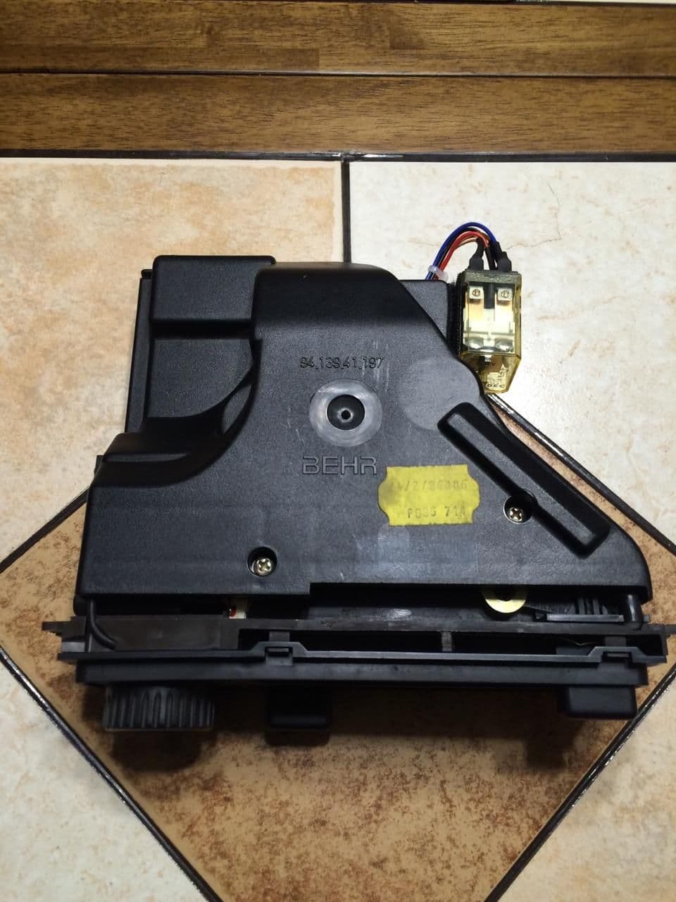
It's been a few weeks but I have managed to replace my relay and have ice cold AC. I wish to thank Dwayne and DrBob (and everyone else) for all their help. It would have taken me three times as long without your help. Here is my repaired unit just before going back in.
Randy

 06-30-2016, 12:55 AM