When you click on links to various merchants on this site and make a purchase, this can result in this site earning a commission. Affiliate programs and affiliations include, but are not limited to, the eBay Partner Network.
I am working on mounting this e3io PC in the GTS and am trying to work out the best power sources for the various things that will be connected to it, so nothing gets switched on or off at a bad time.
If I'm reading the WD right, for the purposes of using an add-a-fuse, the fuses in 1993 that have switched (15) power include 38 through 45, and the X-bus fuses are 33,34,and 35.
But here's where I get confused.
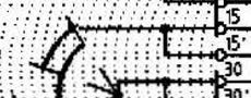
Looking at the 1993 wiring diagram, there are a million wires coming out of the switch:
To some extent I understand the idea of the different buses (15, 30, X) thanks to Alan's electrics primer, but as you can see in the pic above and the connection list below, there are additional buses or connections- 50, R, P, 1, 2
I can see there are 3 wires labelled 30 that are thus +12V coming directly from the battery. If I understand the wiring diagram image, the 'swiper' is drawn in position 0, so only the 'P' "arc" is connected to battery through the 1mm2 green wire to the 'P' terminal of the turn signal switch, so newbs can wonder why only 1 turn signal is on, with the key out.
In position 1, according to the owner's manual, all electric circuits are operational except for the following: turn signals, back-up lights, outside mirror remote control and rear window defogger/defroster.
So in position 1 the battery feeds are connected to the X bus and the 'R' bus, but I can't tell if the 15 bus is connected (???)
Postion 2: Ignition on, steering unlocked. All electric circuits are operational. With the engine stationary, all warning lights will light up for a bulb check.
So in position 2, looks like X, 15, and R busses are connected (?).
And position 3, operating the starter, the arcs look like you have 50, X, and 15 connected. But Alan's description of X-bus is that it's off in the start position (?) I'm a bit lost here....
So what are buses 1 and 2 at the bottom of the switch?
Code:
Bus	Wire	     Connection
50	0.5 YE	     E86, to H21 on CE, to pin 86 of starter relay V
X	4.0 BK/YE	O21 CE, X bus, fuse 34, pin 15 of relay XI- intermittent wiper
X	2.5 BK/YE	interpage G4 to pin 7 of T5 to the X pin of the headlight switch
15	2.5 BK  	Q15 CE panel , 15 bus, fuses 39 to rear wiper switch, fuse 42 to connector U23 to pin 15 of rear window wiper relay
15	2.5 BK  	Q24 CE panel , 15 bus, fuses 39 to rear wiper switch, fuse 42 to connector U23 to pin 15 of rear window wiper relay
30	4.0 RE	     L15 CE panel, to 30 bus, fuse 24 to 30 pin of horn relay and thru T15 to 53a or rear wiper motor, thru fuse 19 to pin 30 of headlight washer rely VII, and thru fuse 18 to ??? To pin 7 of sunroof controller
30	4.0 RE	     L25 CE panel, connected to L15 wire
R	2.5 RE/BK       J63 interpage to pin 1 of noise suppressor to radio
P	1.0 GR	     K4 interpage to P terminal of turn signal/dimmer switch
1	0.5 BK/RE	C30 interpage to Pin1, plug one of digidash - buzzer contact
1	0.5 BK/RE	P25 interpage to pin 85 of relay socket for timing relay (M215, M533)
2	0.5 RE/BK	E26 interpage to 4 wires (1-'square')- pins 16 and 17 (0.75 RE/BK) plug 1 of instrument cluster  (Power to cluster),  pin 3 (0.5RE)
So some extent I understand the idea of the different buses (15, 30, X) thanks to Alan's electrics primer, but as you can see in the pic above and the connection list below, there are additional buses or connections- 50, R, P, 1, 2
I can see there are 3 wires labelled 30 that are thus +12V coming directly from the battery. If I understand the wiring diagram image, the 'swiper' is drawn in position 0, so only the 'P' "arc" is connected to battery through the 1mm2 green wire to the 'P' terminal of the turn signal switch, so newbs can wonder why only 1 turn signal is on, with the key out.
In position 1, according to the owner's manual, all electric circuits are operational except for the following: turn signals, back-up lights, outside mirror remote control and rear window defogger/defroster.
So in position 1 the battery feeds are connected to the X bus and the 'R' bus, but I can't tell if the 15 bus is connected (???)
I don't think it is; The 15 arc doesn't start until position 2.
Postion 2: Ignition on, steering unlocked. All electric circuits are operational. With the engine stationary, all warning lights will light up for a bulb check.
So in position 2, looks like X, 15, and R busses are connected (?).
Agree
And position 3, operating the starter, the arcs look like you have 50, X, and 15 connected. But Alan's description of X-bus is that it's off in the start position (?) I'm a bit lost here....
I think X-bus is off when the starter is engaged, since the arc portion ends before position 3. I think there should be a dot where the X arc line becomes horizontal.
So what are buses 1 and 2 at the bottom of the switch?
I think that is a switch that senses whether the key is in the ignition.
15 is connected in 2 & 3 (ignition) ... not 1
X is connected in 1 & 2 (accessories)
R is connected in 1 & 2 also even though the diagram looks like it is connected in 1, 2 & 3
P is connected in 0 only (drives the parking lamp supplies)
50 is connected in 3 only (starter)
1 & 2 are indeed for the Key in switch - detects just the presence of the key in the slot (for the chime etc functions)

 05-12-2015, 02:24 AM