When you click on links to various merchants on this site and make a purchase, this can result in this site earning a commission. Affiliate programs and affiliations include, but are not limited to, the eBay Partner Network.
My 'rule of thumb' on belt tension is half a thickness deflection with thumb pressure mid-span. So the ribbed alternator belt maybe 1/8" deflection. It's pretty darn tight.
---
Clamp-on Ammeters for DC circuits can be a little spendy. The typical one you use for house or other AC circuits won't give a reliable reading on DC circuits like the battery and alternator. The ones for DC induce a high-frequency field through the cable, and look at distortion of that field to determine current flow. Bottom line: Make sure your clamp-on meter is designed for DC measurements.
In addition, the load in the car splits forward and back at the alternator, so you get to take several readings and put them together to get a total picture of current flow in the car. From the alternator, current flows forward in the car to the ABS connection if you have ABS, and to the jump post and on to the CE panel for most but not all loads. From that same alternator, current flows to the rear to charge the battery, and also to run the fuel pump, injectors, and on S4+ cars the cooling fans, all of which connect directly to the battery positive.
I have access to some very expensive electrical test equipment If I need to hook this thing up to a digital oscilloscope or logic analyzer, it's not an issue. I figured on clamping around the leads directly off the alt B+, that should indicate total load, but I didn't immediately think of checking the loads separately, and that may be very telling. Thanks for the advice.
I've been able to do a little more troubleshooting.
I tightened belt to half a belt thickness deflection with moderate thumb pressure.
No Change
I bypassed any resistance in the heavy battery cable by temporarily adding a heavy cable directly from the alternator B+ to the battery positive.
No Change
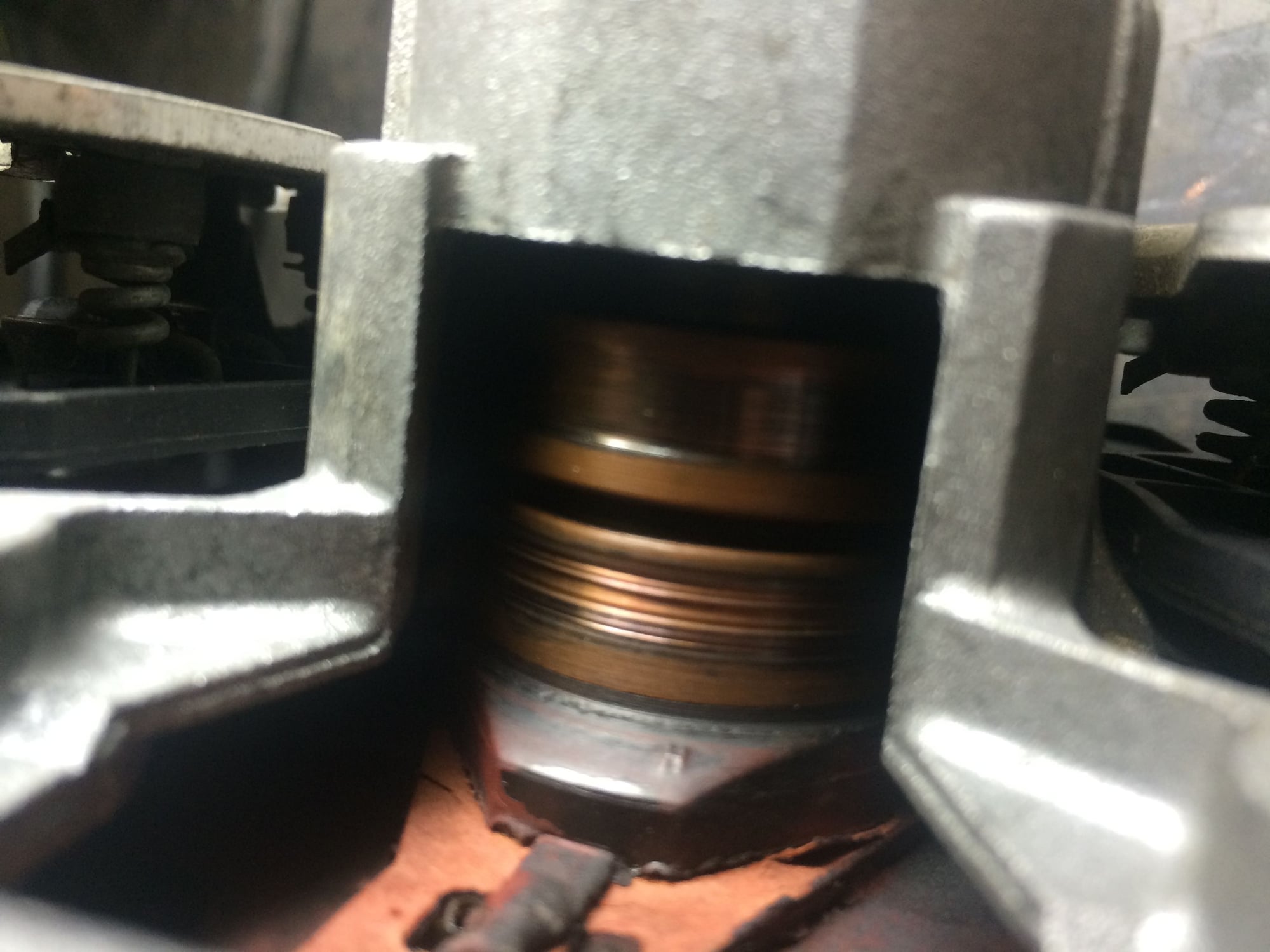
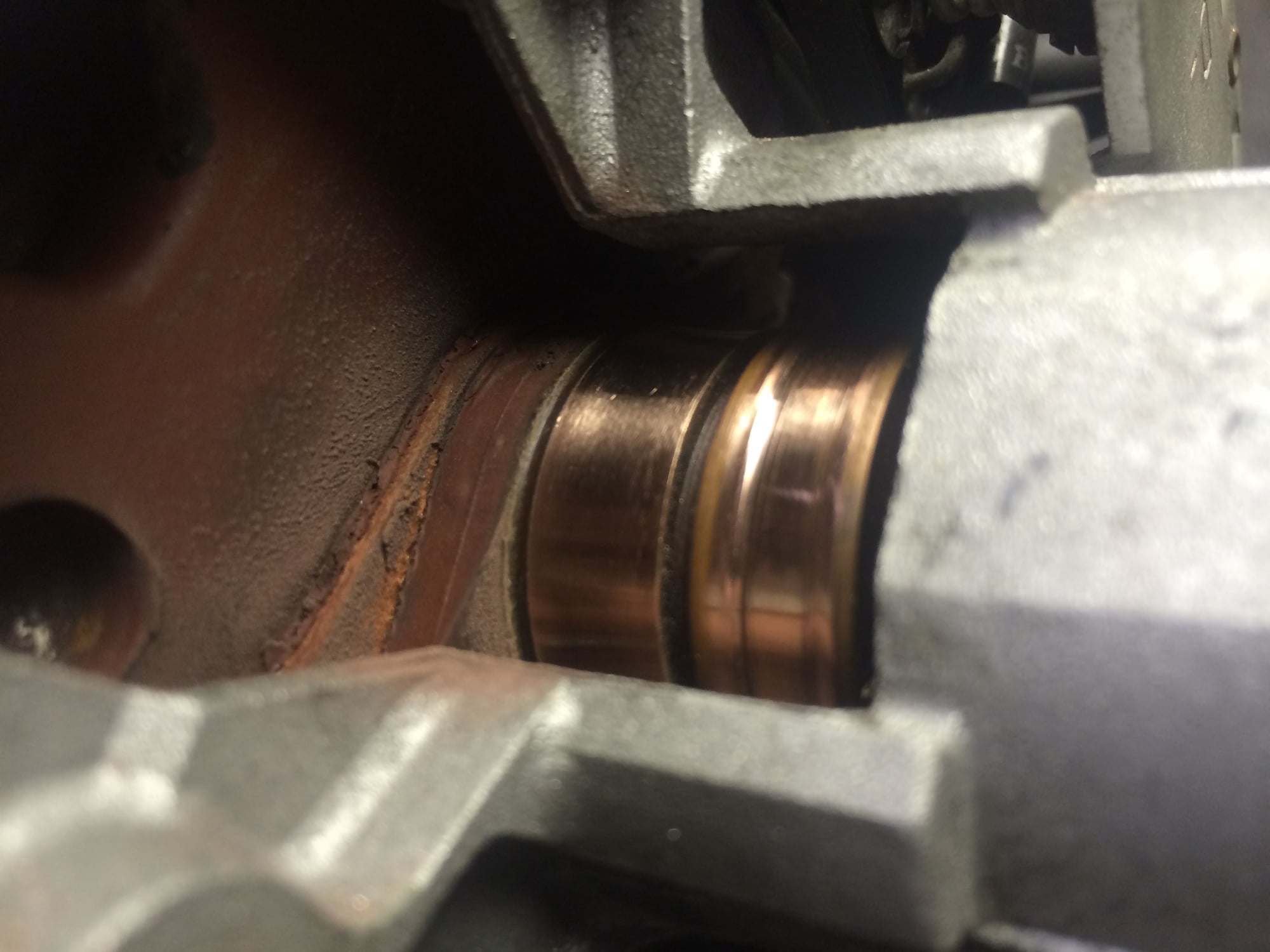
I polished the alternator slip rings to remove worn in ridges:
lower ring has a few knife edges the brush rides on
see right brushes are new and haven't bedded in
ridges removed on a lathe. rings are still perfectly concentric
after all that lathe work, no change to indications listed in first post.
heading in with a clamp ammeter sometime today to see what the loads are on the various power feeds. I still need to R&R the CE panel for a good cleaning
As Before: You seem to be studiously ignoring this obvious step...
Originally Posted by Alan
It seem clear the alternator doesn't charge - except marginally at cold - take it out and take it to a good alternator shop for evaluation (don't just replace - test - you want to know its condition for diagnostic purposes). It's interesting you say the previous alternator did the same thing - but I wouldn't ignore the obvious diagnostic path.
Once you know you have a good alternator - check the exciter line while running at the 14 pin connector (at both engine cold & hot conditions). You want to see that is continually driven high and not drooping when hot.
Alan
Everything you have seen suggests simply an alternator that doesn't generate well - could be rectifier diodes (there are at least 9 - maybe 15) or the regulator. To me your wiring measurements are very ambiguous - but the primary wiring doesn't really sound like the problem here. You are taking a very interesting approach to debug - it may be sound from a theoretical methodology perspective - but is is not the most efficient route to resolving the problem.
As Before: You seem to be studiously ignoring this obvious step...
Everything you have seen suggests simply an alternator that doesn't generate well - could be rectifier diodes (there are at least 9 - maybe 15) or the regulator. To me your wiring measurements are very ambiguous - but the primary wiring doesn't really sound like the problem here. You are taking a very interesting approach to debug - it may be sound from a theoretical methodology perspective - but is is not the most efficient route to resolving the problem.
Alan
I very much see your point. I may well have two weak alternators. Going forward I'm getting the units evaluated by a pro shop in Arlington and cleaning the CE panel while waiting to get them back. These are all I have left on my list.
I realize many times I don't take the most efficient route because I intentionally get into the weeds to learn how things are put together or how systems are designed. The more I know about how things are supposed to work, the simpler it is to troubleshoot when they don't. That's just me and sometimes it drives folks nuts
You bring up as does the alternator guy at metroplex that alternators contain more diodes than I could find. I only found 3. He mentioned there were at least 6 and as many as 12 on new designs. I guess they run them in parallel because a higher current unit would need huge diodes otherwise. Don't know where the rest are hidden, but the shop will figure out whats up in there at any rate.
A three phase alternator will always have a minimum of 6 primary rectifier diodes, sometimes paired for 12 diodes (late model 928 alternators have 12 primary diodes).
There are also normally 3 additional secondary diodes (one per phase) used as a regulator feed on just one polarity (return is through one polarity of the primaries) - this provides the regulator with its own supply.
Oh, I think I get it. The three extra diodes supply DC excitation to the rotor through the regulator.
Yes this is the path for the rotor field current via the slip rings/brushes - The regulator controls the field current magnitude (usually on the ground side) to achieve the voltage set-point. You can see this configuration in the wiring diagrams for 1984 & later years... configurations change between Star(Wye)/Delta but are basically similar in concept for all years.
Update. I pulled the Paris Rhone and put the Bosche back in. Results are the Bosche unit now puts out 13.5 volts at idle. So whatever I did while the PR unit was in made the system better I guess.
I turned the PR unit into Metroplex Alternator and Starter in Arlington TX and they found at least one bad diode if not a bad winding. Won't know for sure, but a new rectifier bridge is inbound and 90% certain that will restore normal operation.
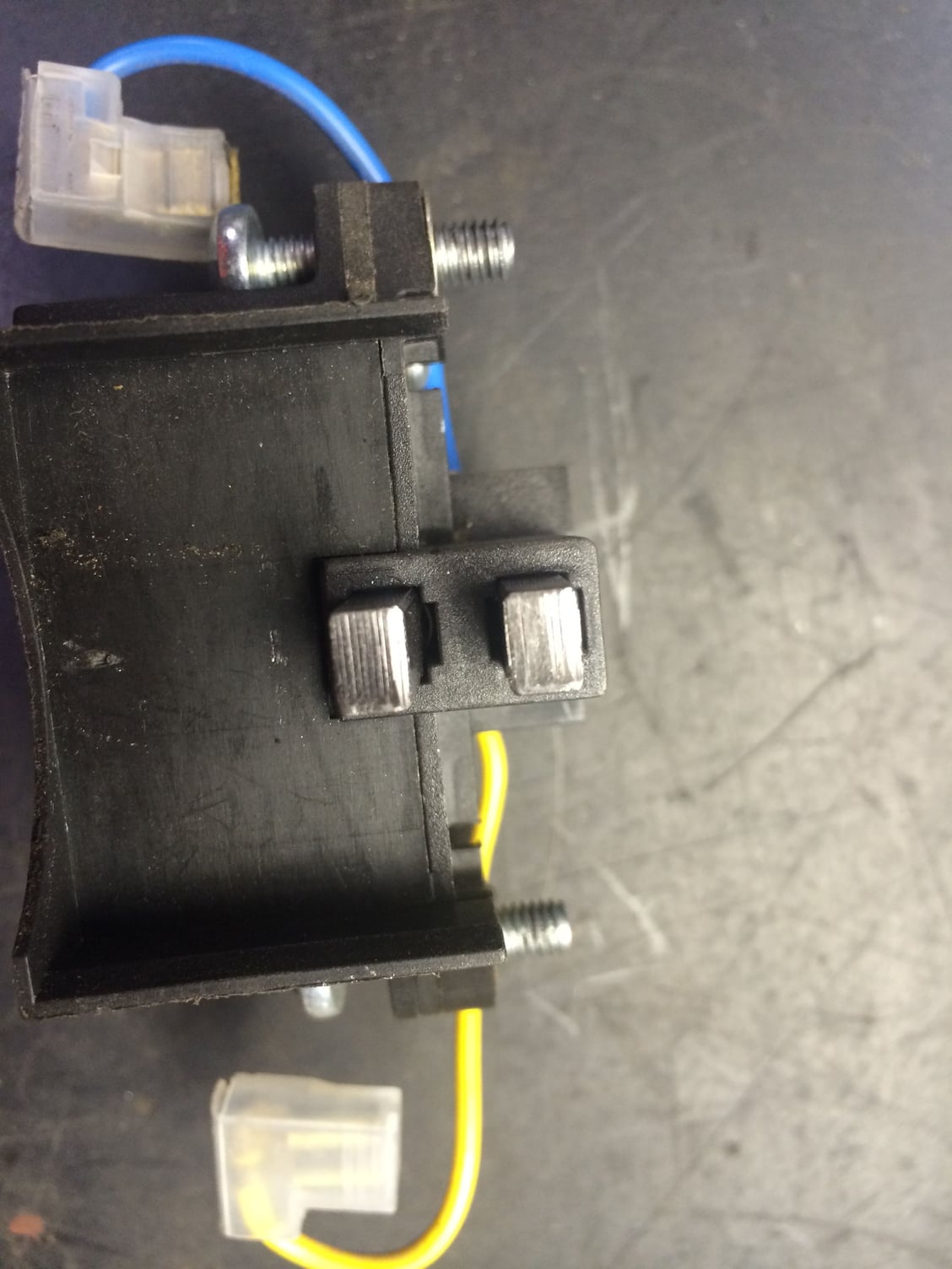
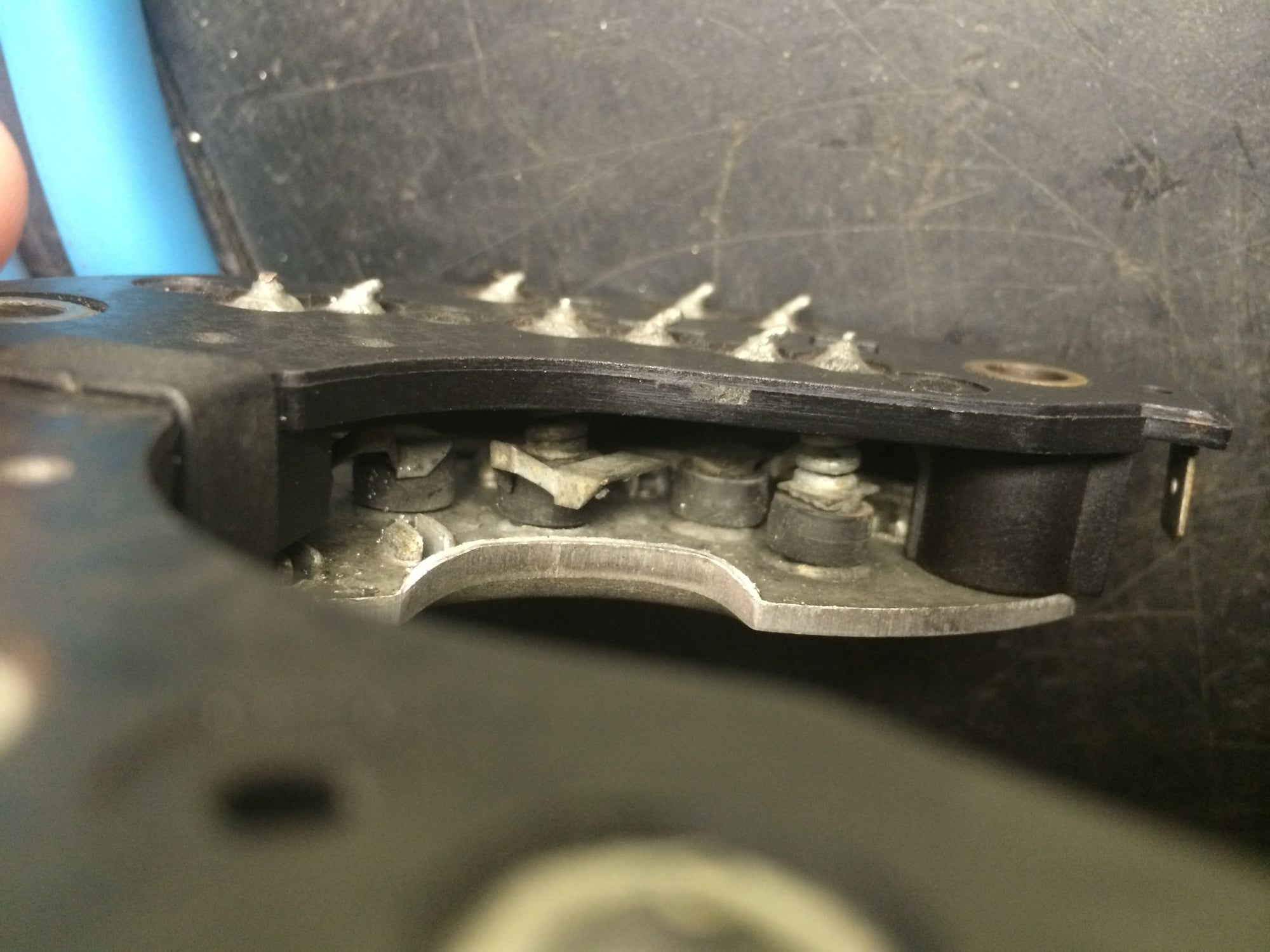
Got the PR unit back to from metroplex and David found one of the button diodes on the rectifier assembly missing and the other in parallel with it was unsoldered. This original PR rectifier had 12 button diodes for output rectification and three axial diodes for the field current. Two parallel diodes out means 1/3 of the windings were open and useless. I think this means the unit was down to 66% rated output. He turned the contact rings which remained within limits for diameter and replaced the rectifier assembly with a new valeo rectifier which has 6 rectification diodes of much higher capacity and the same three for the field current. The newer style unit is much less sensitive to overheating than the original. Still though, the unit needs fresh air. I suppose this is a case for making sure the factory cooling is intact.
you can see the metal tab hanging free. There should be a button diode under it.
I installed the PR unit and verified proper operation. Voltage is stable at 13.8 at low idle.

 12-03-2014, 01:50 PM
 If I need to hook this thing up to a digital oscilloscope or logic analyzer, it's not an issue. I figured on clamping around the leads directly off the alt B+, that should indicate total load, but I didn't immediately think of checking the loads separately, and that may be very telling. Thanks for the advice.


 Thanks again everyone!
