
An 87 CE Panel Refresh Picture Thread from a Second-Timer
 09-28-2014, 08:14 PM
#1
Burning Brakes
Thread Starter
After buying a couple of cans of DeoxIT spray, I thought I would refresh the CE panel on my '87 928S4.
It is a very simple, but time-consuming, job.
First, unscrew two thumb screws on the the tool tray in the back hatch.
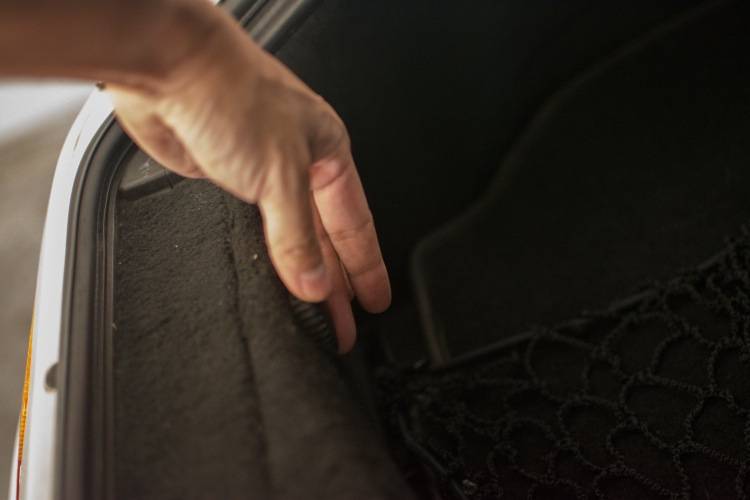
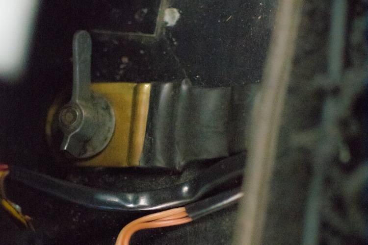
Next, remove the wing nut that connects the battery ground-strap to the chassis.
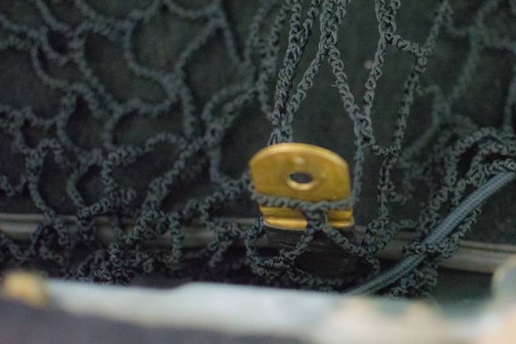
The '87 has a cargo net. I use it to hold the ground strap away from anything that could ground the electrical system.
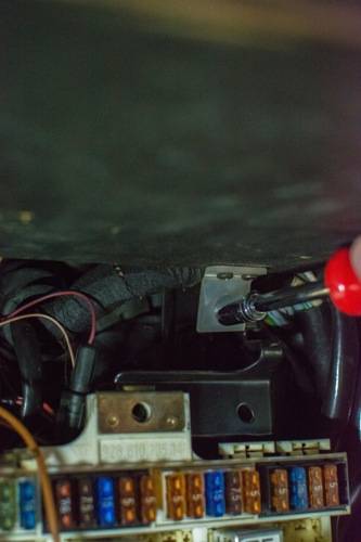
Next, there are two (one on each side) 8mm nuts that hold the parcel tray in the passenger footwell. Remove both.
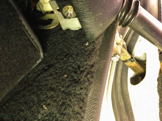
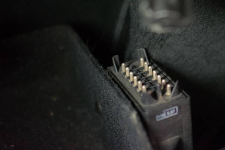
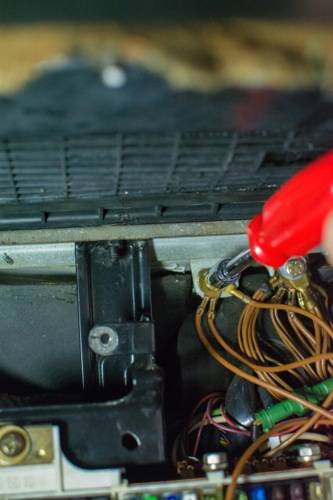
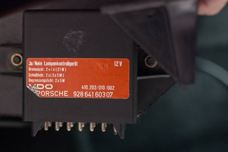
The bulb control module is attached to the package tray.
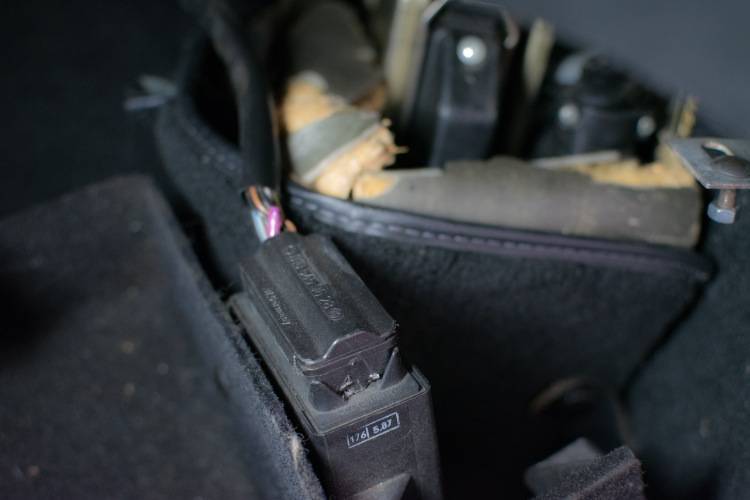
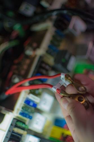
Better to disconnect it, to have more room. I used a flathead screwdriver and gently pried the female end of the connector from the male end of the module.
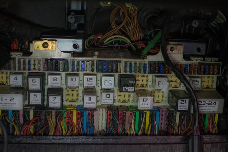
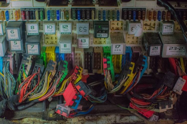
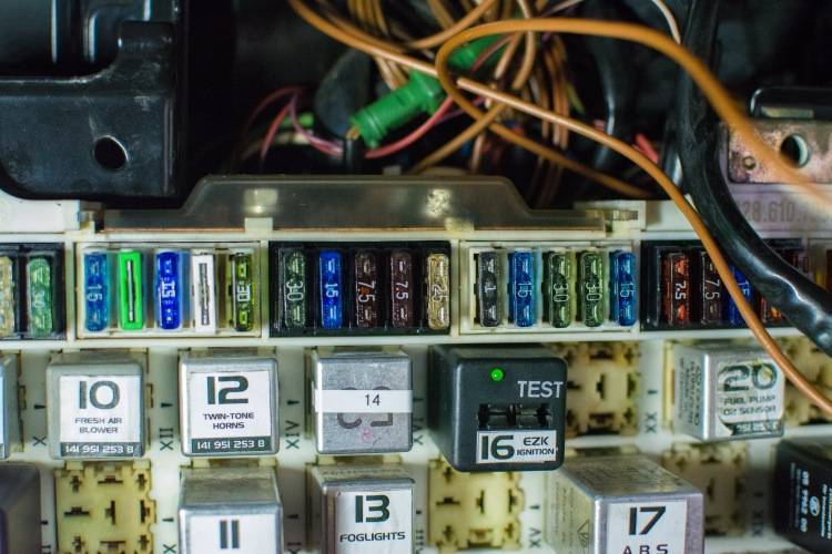
This is the Central Electric (CE) Panel.
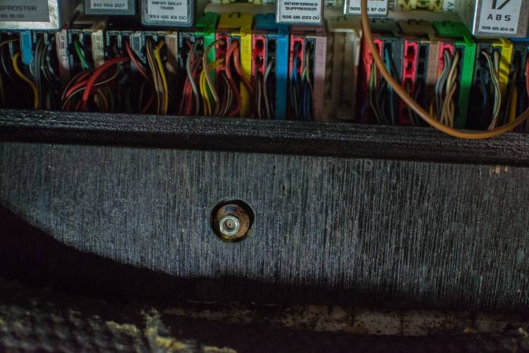
This is the lower wooden cover for the CE panel.
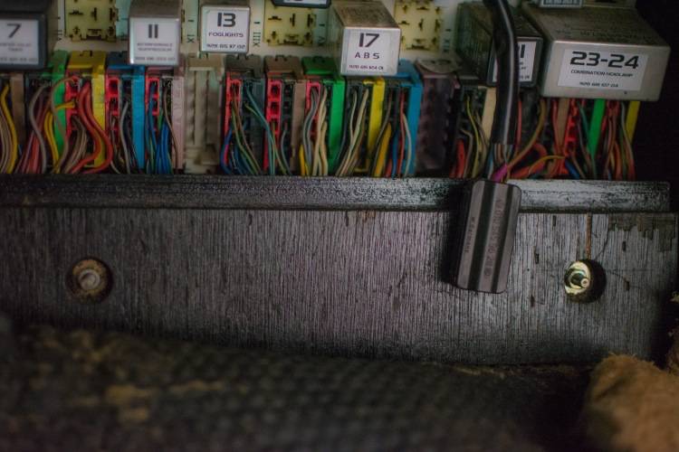
It has two 10mm nuts. Put them in a safe place, along with the washers, and remove.
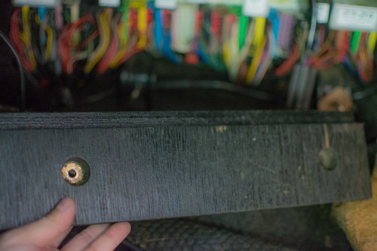
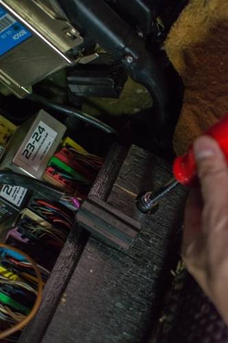
The upper wooden cover for the CE panel swivels. There are two 10 mm bolts (one on the left, one on the right) that need to be removed.
The top of the CE panel has two Phillips head screws that hold it in place. (Mine was missing one.) Remove the two screws.
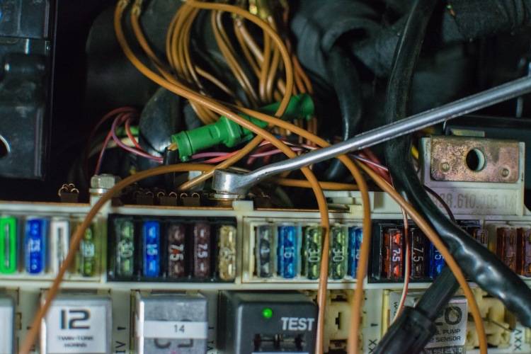
The power to the CE panel is at the top. Remove the translucent plastic cover that protects the positive terminals by pinching them at the sides of the plastic.
Using a 10mm wrench, unscrew both power wires (in red insulation.)
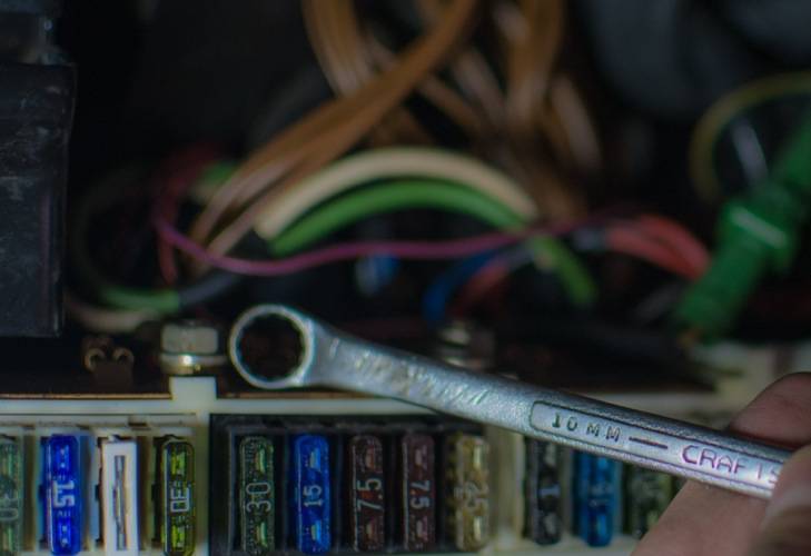
After freeing the power wires, I put the 10mm nuts back onto the top of the CE panel, so as not to lose them.
I labeled the wires "left" and "right."
It is a very simple, but time-consuming, job.
First, unscrew two thumb screws on the the tool tray in the back hatch.
Next, remove the wing nut that connects the battery ground-strap to the chassis.
The '87 has a cargo net. I use it to hold the ground strap away from anything that could ground the electrical system.
Next, there are two (one on each side) 8mm nuts that hold the parcel tray in the passenger footwell. Remove both.
The bulb control module is attached to the package tray.
Better to disconnect it, to have more room. I used a flathead screwdriver and gently pried the female end of the connector from the male end of the module.
This is the Central Electric (CE) Panel.
This is the lower wooden cover for the CE panel.
It has two 10mm nuts. Put them in a safe place, along with the washers, and remove.
The upper wooden cover for the CE panel swivels. There are two 10 mm bolts (one on the left, one on the right) that need to be removed.
The top of the CE panel has two Phillips head screws that hold it in place. (Mine was missing one.) Remove the two screws.
The power to the CE panel is at the top. Remove the translucent plastic cover that protects the positive terminals by pinching them at the sides of the plastic.
Using a 10mm wrench, unscrew both power wires (in red insulation.)
After freeing the power wires, I put the 10mm nuts back onto the top of the CE panel, so as not to lose them.
I labeled the wires "left" and "right."
 09-28-2014, 08:23 PM
#2
Burning Brakes
Thread Starter
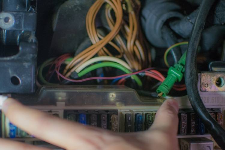
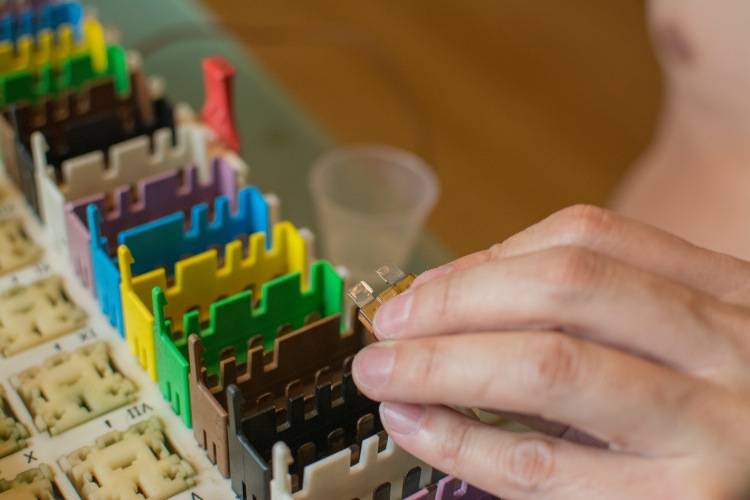
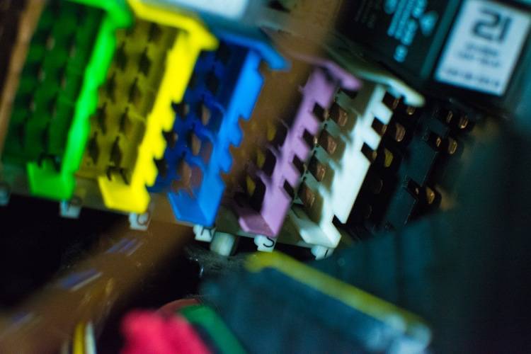
At the bottom of the CE panel, there is a red tab that is pushed down and pulled out. This frees the colored connectors from the CE panel.
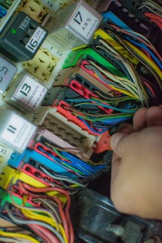
Gently lift the tab on each connector, then gently pull the connector out. Repeat.
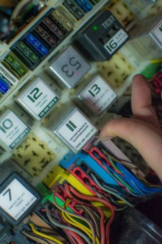
When you are done, the CE panel looks even more chaotic than before.
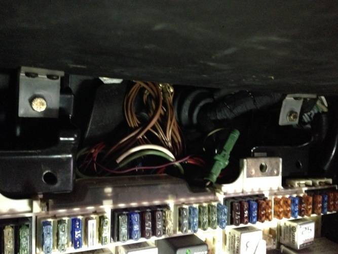
Disconnect the ground wires from the left ground point, above the CE panel. 10mm socket.
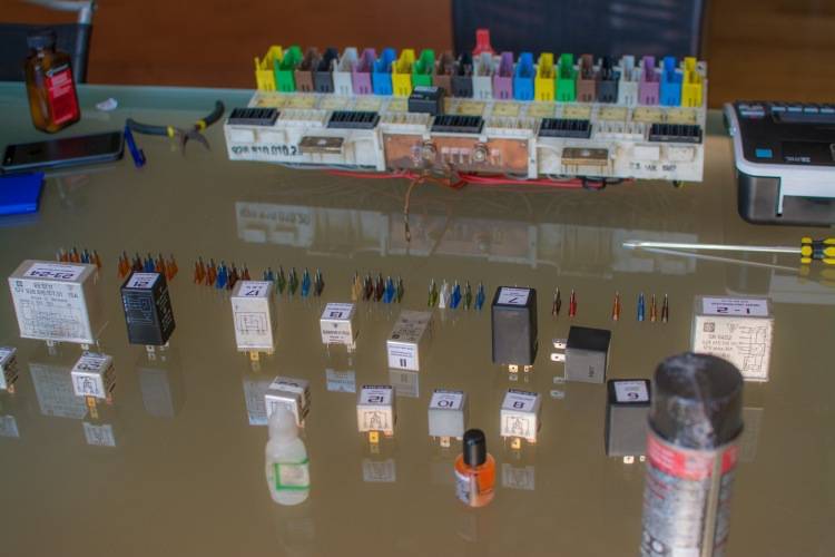
Now you are ready to remove the CE panel from the passenger footwell. I put the CE panel- to the delight of my wife- on the kitchen table.
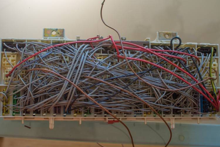
The back of the CE panel looks like grey spaghetti.
I removed all of the fuses.
Then, I removed all of the relays.
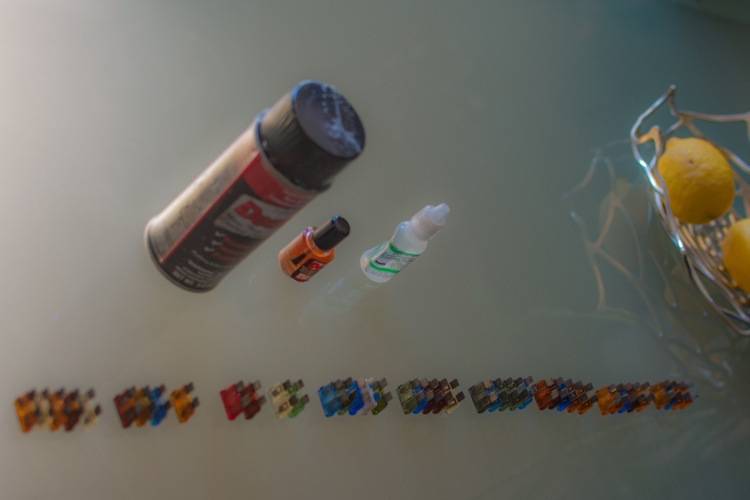
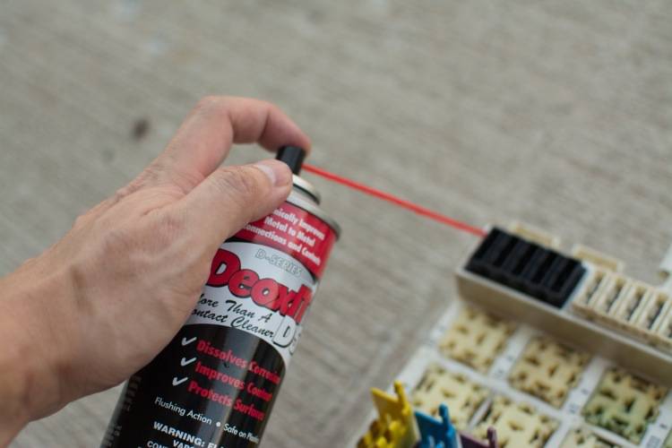
Taking the CE panel outside, I sprayed a short burst of DeoxIT onto every electrical connection in the CE panel. I waited 10 minutes, and then did it again.
Next, I diluted one part Stabilant-22
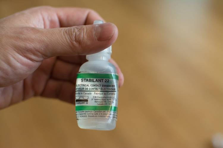
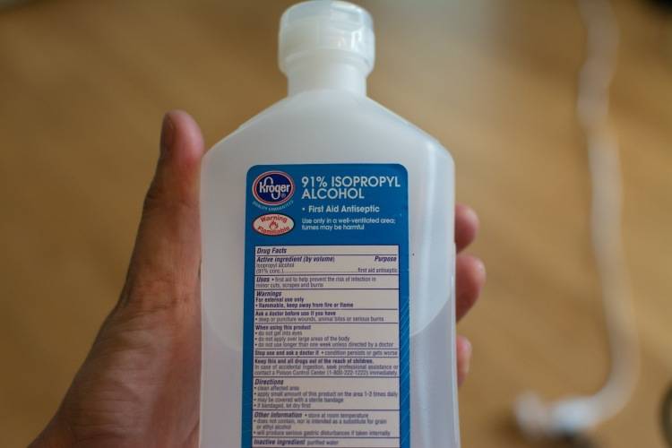
...with four parts Isopropyl Alcohol...
And after gently cleaning each surface of every fuse and relay terminal with a dremel wire brush, painted the diluted Stabilant-22 onto each terminal.
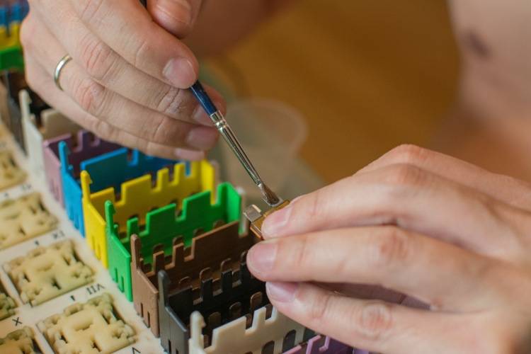
I also painted each terminal on the CE panel with the diluted Stabilant-22.
Then, I put each fuse and relay back into the CE panel.
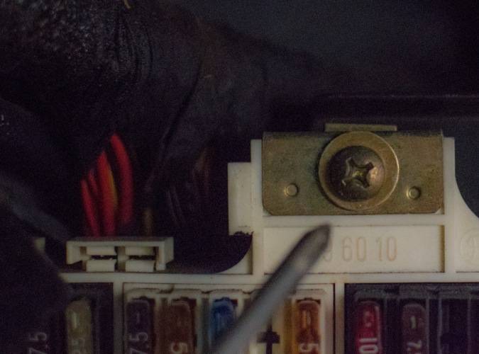
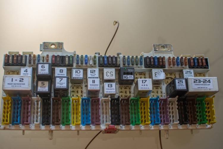
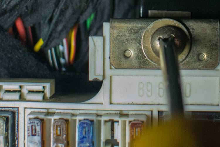
Now, time to return the CE panel to the passenger footwell. There are two plastic nubs at the bottom of the CE panel (the one pictured below is between "R" and "S." The nub should sit in an appropriately-sized indentation in which it fits. Make sure it is seated properly.
Gently lift the tab on each connector, then gently pull the connector out. Repeat.
When you are done, the CE panel looks even more chaotic than before.
Disconnect the ground wires from the left ground point, above the CE panel. 10mm socket.
Now you are ready to remove the CE panel from the passenger footwell. I put the CE panel- to the delight of my wife- on the kitchen table.
The back of the CE panel looks like grey spaghetti.
I removed all of the fuses.
Then, I removed all of the relays.
Taking the CE panel outside, I sprayed a short burst of DeoxIT onto every electrical connection in the CE panel. I waited 10 minutes, and then did it again.
Next, I diluted one part Stabilant-22
...with four parts Isopropyl Alcohol...
And after gently cleaning each surface of every fuse and relay terminal with a dremel wire brush, painted the diluted Stabilant-22 onto each terminal.
I also painted each terminal on the CE panel with the diluted Stabilant-22.
Then, I put each fuse and relay back into the CE panel.
Now, time to return the CE panel to the passenger footwell. There are two plastic nubs at the bottom of the CE panel (the one pictured below is between "R" and "S." The nub should sit in an appropriately-sized indentation in which it fits. Make sure it is seated properly.
09-28-2014, 08:33 PM
#3
Burning Brakes
Thread Starter
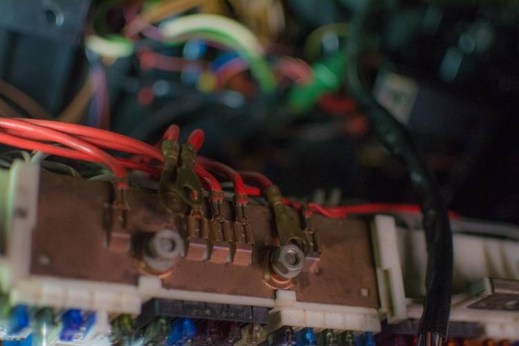
The power wires need to be draped over the CE panel before screwing it back in place.
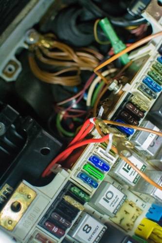
The ground wires do, as well.
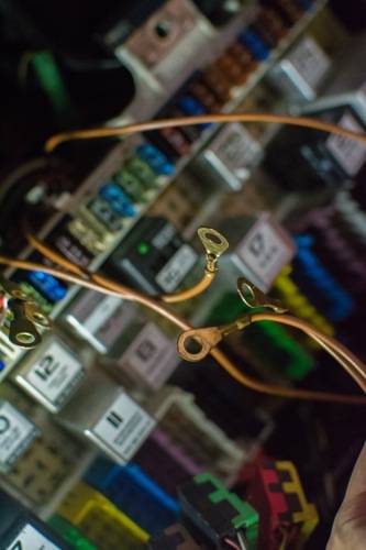
Secure the power wires onto the top of the CE panel. 10mm.
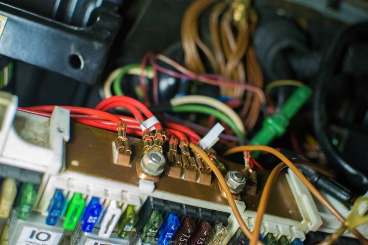
(Also, secure the ground wires to the left ground point- MP V)
Secure the CE panel to the floor with a Phillips screwdriver.
Restore the translucent positive terminal cover.
The lower wooden cover goes on, with washers. Two 10mm nuts.
The upper wooden cover (the one that swivels) goes back on- two 10 mm bolts.
Almost done.
Restore the package tray, secure the two 8mm nuts.
Reattach the bulb control module.
Reattach the ground strap to the chassis via the wing nut at the back of the trunk, restore the tool tray, and you are good to go.
The ground wires do, as well.
Secure the power wires onto the top of the CE panel. 10mm.
(Also, secure the ground wires to the left ground point- MP V)
Secure the CE panel to the floor with a Phillips screwdriver.
Restore the translucent positive terminal cover.
The lower wooden cover goes on, with washers. Two 10mm nuts.
The upper wooden cover (the one that swivels) goes back on- two 10 mm bolts.
Almost done.
Restore the package tray, secure the two 8mm nuts.
Reattach the bulb control module.
Reattach the ground strap to the chassis via the wing nut at the back of the trunk, restore the tool tray, and you are good to go.
09-28-2014, 08:37 PM
#4
Nordschleife Master
Nice writeup. I used the one on Sharkskin's page and it was also easy to follow.
I made sure that I labelled all of the letter coded plugs. It was when I was plugging them back in that I noticed that each plug already had the proper letter molded into the plastic.
You might want to invest in a simple workbench. Wives will only tolerate so much.
I made sure that I labelled all of the letter coded plugs. It was when I was plugging them back in that I noticed that each plug already had the proper letter molded into the plastic.
You might want to invest in a simple workbench. Wives will only tolerate so much.
09-28-2014, 09:01 PM
#5
Rennlist Member
Nice write up. Thans for doing this. Did you notice a difference after the treatment?

Trending Topics
09-29-2014, 12:46 PM
#8
Electron Wrangler
Lifetime Rennlist
Member
Lifetime Rennlist
Member
Its good to see a good photo write up on the later panels to go along with Dave's for the early panels.
The two power wires to the top of the panel both go to the jump post - you can fit them in either location - just whatever reaches best - makes no difference.
Be careful with the top retaining clips for the plugs - they are very brittle - if you stress them too far upwards they will snap off. Best way to remove the plugs is to make a puller tool - a paperclip works. The plug bodies have 2 diagonally opposed tabs that stick up with a small hole in each. Open up the paperclip, bend the paperclip into a U shape, then bend a small hook into each open end with pliers. Pop the hooks though the tabs and then you can pull the plugs out straight from the panel with one hand while easing the retainng tab with a flat blade. Don't pull on the wires.
The plugs & panel have a coding scheme built in to ensure that you cannot install a correctly colored plug in the wrong socket - it can't be done, everything is already labelled - so just match colors.
Alan