
1978-1986 US versus ROW Cylinder Heads; Valve, Port and Combustion Chamber Sizes
 06-29-2014, 01:50 PM
#1
Burning Brakes
Thread Starter
Join Date: Aug 2013
Location: Northeast USA
Posts: 948
Likes: 0
Received 0 Likes
on
0 Posts
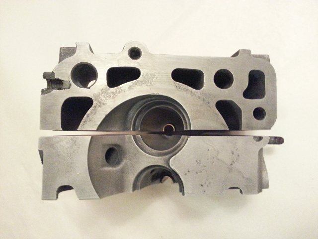
I just thought I would post a thread to show the visual and basic measurement information I've gathered though empirical observation with regard to differences in cylinder heads from M28.01, M28.20 and M28.22 engines. The measurements are approximate hence the "~" before the numbers. I wasnt' motivated to pull the valves from the head to get a proper engineering measurement. My point is to show the combustion chamber differences in particular and the matching intake/exhaust port dimensions. I have not down a cc sizing on the chambers as of yet but you can see clearly from the pictures the differences and the orientation of the valves, sparkplugs and quench.
M28.01 & M28.20:
Intake Valve: ~43mm
Exhaust Valve: ~38mm
Intake Port: ~38mm
Exhaust Port: ~35mm
Intake Runners: ~38mm
Throttle Body: ~73mm inside diameter
M28.22:
Intake Valve: ~45mm
Exhaust: ~40mm
Intake Port: ~40mm
Exhaust Port: ~37mm
Intake Runners: ~40mm
Throttle Body: ~83mm inside diameter
The most outstanding differences as expected are in the combustion chamber shape and pocket locations and the throttle body is a complete 10mm larger in the M28.22 to support the additional 2mm increase per port. The shape and size of the chambers support the advertised compression ratios are as follows: M28.01 at 8.5:1; M28.20 at 9.3:1 and the M28.22 at 10.4:1.
I just thought someone who wants to see the differences in these 16V heads would find this basic info interesting.
Pictures:
Cheers,
Fronkensteen
Last edited by Fronkenstein; 06-29-2014 at 05:12 PM. Reason: Clarify measurement
 06-29-2014, 02:11 PM
#2
Nordschleife Master
Thanks for posting. Great reference material.
People will say "2mm ain't much" but area varies as the square of diameter. Some area is also wasted and wall area slows flow down. A little bit more of real free area for flow makes a big difference.
The throttle is a lot. The 73mm has an area of 41cm^2 and the 83mm has an area of 54cm^2. That's 30% more.
06-29-2014, 04:52 PM
#3
Burning Brakes
Thread Starter
Join Date: Aug 2013
Location: Northeast USA
Posts: 948
Likes: 0
Received 0 Likes
on
0 Posts
Glen,
Thanks for adding the math - I'm too lazy:-) What I want to know is the flow characteristics of the K-jet flow meter flapper. Be interesting to see if a K-jet with a 83mm TB and larger outlet nozzles could flow enough fuel and air to make 310+ HP. Maybe someone has or knows what the flow specs are on the K-jet. Going to run K-jet temporarily on Inga until I have the MS3PRO OEM ready for bolt on.
Cheers,
Fronkensteen
06-29-2014, 05:02 PM
#4
Burning Brakes
Thread Starter
Join Date: Aug 2013
Location: Northeast USA
Posts: 948
Likes: 0
Received 0 Likes
on
0 Posts
Well given the Chevy 273 and 302 are very happy with a 600 CFM carby at 10:1 compression I'd say that a 4.7L (287 CI) NA would be happy with 650-700 CFM of flow. Carl uses 850 CFM compressors on his 4.5's there were running K-jet. So now just need to see what the stock K-jet can pump.
06-29-2014, 05:59 PM
#6
Burning Brakes
Thread Starter
Join Date: Aug 2013
Location: Northeast USA
Posts: 948
Likes: 0
Received 0 Likes
on
0 Posts
Thanks Iceman, yes so true. Basically what I've read from several sources is that the K-jet will flow enough air with a larger TB. But you have to richen up the mixture a tiny bit and you can play with the metering block fuel return circuit and outlet nozzles, but there are limits.
I am going to put an AFM right at the crossover pipe to keep an eye on things anyway so as not to lean her out. Once the MS3 is in it will be a new game. Hopefully a bit less finicky and more spirited. Certainly fuel efficiency will be increased if I keep my foot out of it - riiiiight:-D
After staring at these spiderworks intake systems, I really wonder if it had more to do with aesthetics and character than performance. There is certainly enough room to shoehorn a more conventional intake like a 5.0 Cobra. Granted the plenum size would suffer, but damn these spiders are whacky. A case in point is how do broken rings from #1 cylinder make there way into #5 and #8? There is some weird science there
Fronkensteen
06-29-2014, 06:07 PM
#7
Nordschleife Master
The spider is cool and functional.
Lots of people (me included, ~335) are making over 310hp with the K-jet. The dyno graphs don't show any fuel problems at the power peaks and had room for being richer. More power requires getting more air through the engine. The fuel is there.
Your question does make me wonder at what air flow rate the arm for the fuel distributor will be maxed out.
Trending Topics
06-29-2014, 08:17 PM
#8
Burning Brakes
Thread Starter
Join Date: Aug 2013
Location: Northeast USA
Posts: 948
Likes: 0
Received 0 Likes
on
0 Posts
I'd be happy with ~335HP with little mods like bigger TB, dual exhaust, S2 headers, CIS tuning, electric fans, AC delete, smod delete, egr delete, road draft ventilation and whatever else I can conjure up.
Fronkensteen
Fronkensteen
06-29-2014, 09:16 PM
#9
Nordschleife Master
I think part of it is how close to the edge can you safety tune CIS vs LH.
Maybe too simple, but measure the force required to fully depress the meter flap on a CIS car, then calculate the square inches and that should have some relation to the pressure drop. Or just measure the pressure drop at some known high flow state.
If its rwhp 335 from a 4.7L seems very optimistic given our limited max rpm, crank HP easy.
09-01-2014, 10:03 PM
#11
Burning Brakes
Thread Starter
Join Date: Aug 2013
Location: Northeast USA
Posts: 948
Likes: 0
Received 0 Likes
on
0 Posts
This is what one does on a Labor Day weekend when one gets bored and his tools start to talk to him:-D Thought a cut-away of a large port head would be useful for those of us backyard porting folk.
Wall margins are as thin as 3mm. Proceed with extreme caution! Also note that there is an internal gap between intake and exhaust ports bringing water with 15mm or less of the valve seats apron. Also note how thin the margin is at the spring shim seat. For the life of me I just don't understand the point of the iron sleeves in the exhaust ports. Would love to hear the engineering reasoning behind that one. I could understand something on the face of the port but not on the inside.
Fronkensteen
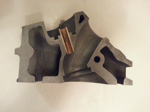
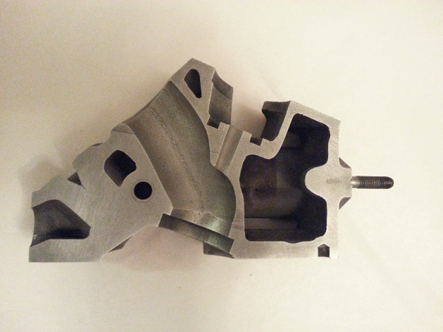
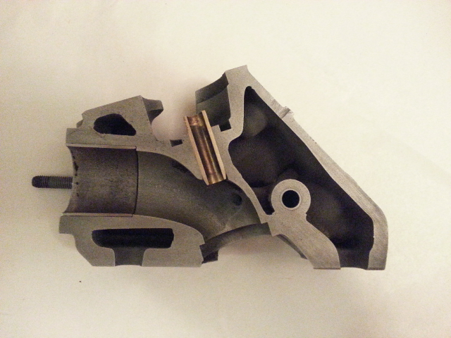
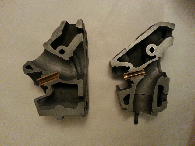
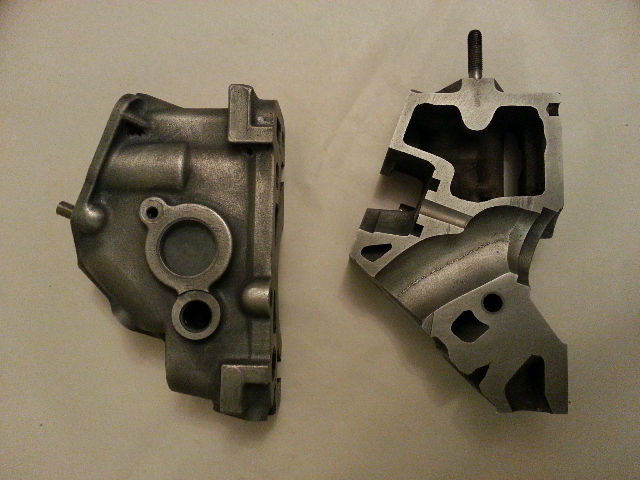
Last edited by Fronkenstein; 09-02-2014 at 09:26 AM.