When you click on links to various merchants on this site and make a purchase, this can result in this site earning a commission. Affiliate programs and affiliations include, but are not limited to, the eBay Partner Network.
Jerry, I have been watching you develop this from the beginning and have been loving watching how your thought process has evolved. Also love how well you can bounce back ideas that others give you.
Now it's my turn to throw an idea out there. This is a very simplified drawing done in paint but I think it will get my idea across. And you have probably had the same thought I would bet. If you were to use a male/female form and make the tube in 2 pieces I think doing something like this would make it aesthetically pleasing. In the "female" form you would just have to add a small indent to the ends that is the thickness of the material you are using and then leave the male form at the correct size. They should fit together snugly and I imagine you could get it near seamless after a try or 2. Would also make gluing together easier. I don't know how well this idea would work with the venturi reduction area though. Again this is just a thought.
Thanks Brad. That idea had actually occurred to me, at least in this latter idea exercise, but I was initially stumped about how to make the male form(s) since each will need to be slightly more than half by about half of the overlap. This is an overlap joint as opposed to a butt joint or the flange joint we have been kind of discussing.
Now however, since I think we are on the same page, at least in respect to the male form, which will have to be turned on the lathe and basically in two pieces, now I think it would be turned in three pieces including the two basic halves but with a third piece in between them that is as thick as the width of the overlap. Then when that is done, the work piece will be taken apart and another same third piece will be inserted and then turned again to match. Now we will have two identical mid pieces; so one will then be split down the middle longways with a kerf twice the thickness of the plastic material, and glued back together. Then it will be glued to one of the basic halves leaving the jog needed; or it can be widened instead and glued back on which will make the jog outward instead of inward, and that might me necessary in order to form it and take it off the form. The other center spacer will just be glued onto the other half. Or, maybe there could be a little of both -- a little positive on one form and a little negative on the other.
Then do it all again for the other side, at least in respect to these tubes for the 85-86 cars. And then put the kink in each of them in some manner.
Now, I am really puzzled about why you guys are still talking about using a rigid female form in this process. I had hoped by now you would all have seen that this process we are discussing with the halves of the male forms will be fully accomplished with the vacu-form process. The ambient air that pushes the soft heated plastic onto the form will do a perfect job of it and leave no marks. And it comes free because it is always there, except where you have to remove it momentarily from under the forms, and it always comes in the exact shape needed, and it even allows for the thickness of the material, whatever it needs to be. And the process is already available, at least at my Plastic Guy's place, so I wouldn't have to make it like I have done for the hanging tube method I am currently working on.
Darn. Now I have finished my first cup of coffee and am working on my second, so my brain has come a little more fully awake. In going through this process in my head after I posted just above, it occurs to me that this is not going to work, at least to the extent of having corrugations, and I think we are going to have them, because of the thickness of the material. For them to mate together in the corrugation areas one half needs to nest into the other half which means that the corrugations need to be male and female -- one smaller to fit into the other larger -- and they are both going be the same.
I don't think I want to go to the trouble to try to make one of the two center pieces of each form larger or smaller so they will nest, but that is what will have to be done.
Wait! My brain is coming around more now. I don't know why it wont let this stuff go so I can think about my other projects I need to work on today, but I just figured out how to adjust the turning of the center section on the second one to be made as described above, and it actually turns out pretty simple. Just turn the corrugation groves slightly narrower on it!!!!!' Done. They will still be the same height and depth since that material allowance is made up in the offset, so all they need is a little more room fore and aft longways with the form.
I would be turning the corrugations with say a quarter inch round nose router bit, so I would turn the narrower groves in the second center section with a bit smaller by twice the finish thickness of the tube material. I may have to have the tooling made unless the right size can be found off the shelf; or I can fudge it a bit in turning to get the correct allowance.
Yes it is, Mike, and thank you for asking. The thing that put this one on the skids was how to form the tubing needed to form the intake tubes. My thought process got so complex and doubtful that I finally let something else take over my thought process and set this one aside.
However, the thank you is because as I was scrolling down the last page to see what you had posted, the simple solution about the tubes just popped into my head. Now I am anxious to give that a try as soon as I can fit it in. My prior method was going to be very hard to handle and was going to give rise to only one tube every three or more days. With what I now have in mind I think I can make as many tubes as I can make the simple tube jig for.
I'll let you know if it works.
Last edited by Jerry Feather; 04-11-2016 at 11:11 AM.
Thanks Jerry, this thread "Modular Late Front Spoiler Project" brought back thoughts of your intake thread.
You take on amazing projects and appreciate everything.
This project is still kind of alive, but got put on the back burner for various reasons. The things that have put me kind of on hold with it include the method to fabricate some ABS tubing to use to form these tubes with, a manner to put the slight kink or bend in them after they are formed, and just how I am going to get the plastic to shrink around the small diameter of the form in the forming process, when I get to it.
I see that I had thought of a simpler means to make the tubes, but now I have actually forgotten just what that was. I think it still involved working with the plastic in its stiff and flat form while attempting to glue it into a tube. My first approach was pretty complicated and involved the development of some extensive tooling, and the second I think involved something less in the way of tooling.
This morning, however, in working on the Radical Custom project as it relates to the interior work and the application of my version of the Pascha design to leather, and thinking thru the use of the Mangle Ironer I have inherited, it occurs to me that the Mangle might well lend itself to heating this plastic in a way that will allow me to roll it into a tube that can then be glued much more easily to itself. Now I have to go check it out some more to see if it will get hot enough and if it is wide enough to run the full length of plastic thru it to soften. Or maybe, now that I think about it some more, I might be able to run it thru endways and then wrap it around some kind of cardboard core or cob to give it the tube shape that can then be glued more easily after it has cooled into that shape.
I still need to figure out how to bend the finished tubes, unless maybe they will simply bend themselves as needed when installed. So, the wrinkles or webs will just have to wait until I can put one in the oven.
Bump. This project may now fit into what seems to be some kind of resurrection phase for me since I have two other old projects that are coming back to life along with the finish up of the new Early Belly Pan project that is going to "press" real soon.
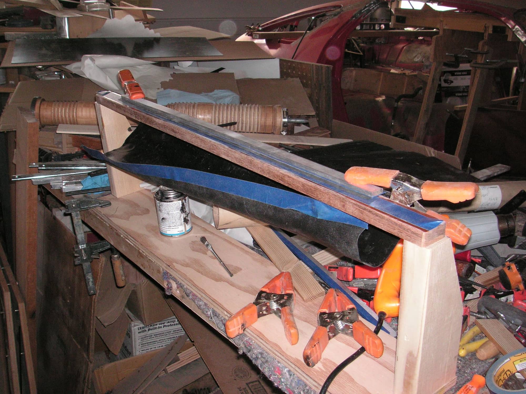
I spent some time last weekend trying to figure out how to make the tube blanks for forming these intake tubes. I didn't have any better idea about how to do it; and I didn't even remember just what I had been thinking before, so I thought I would just start putting some things together to see if some kind of workable process might begin to take shape. It didn't. I worked up a kind of basic forming base with a long cross bar of wood and then clamped a sheet of plastic to it and then tried to see just how the plastic might be rolled into a tube and glued. The plastic is very stiff so that really didn't work. There was just no way to hold it in place to be glued and then clamped to cure. Then I thought I might use my heat gun to kind of roughly roll the plastic into a tube, but that didn't work either since the plastic pretty much goes everywhere.
I left it there but then began thinking about using the heat gun, but setting the plastic up so that the heat would be focused only in a strip longways and thereby much more controlled. I think that might actually work, but will be a lot of work since it will need to be done about 5 or 6 places around the plastic in order to end up with a kind of 5 or 6 sided tube. The shape of it will not matter since if I can still get it over the male form it will be reformed into the shape of the form from whatever it started as.
Then I went to my plastics guy's place to check on my standing to form some Cowl Covers and in the process I told him what I was trying to do and asked him if he had any ideas. Right off he mentioned something about using a sheet of steel rolled into shape, but then my brain took over and I didn't quite understand what he had in mind for it. Since then and through the night my brain took over and has now developed what I think will be a successful means of making the tubes to then be formed. It's going to take a length of aluminum irrigation tube/pipe worked up to roll the plastic in and then set up to glue the edges together. Right now that is all in my mind so I can't show a picture, but I do have a picture of the mess I made last weekend.
Am I right in assuming that the factory items are extrusion blow molded? A quick look at them and I think the seam is just from the mold, rather than actually joining the edges of the tube?
Am I right in assuming that the factory items are extrusion blow molded? A quick look at them and I think the seam is just from the mold, rather than actually joining the edges of the tube?
Hi Hilton. Interesting question. I hadn't given that much thought because it really doesn't matter to me. I have to do this kind of thing in the way that I might be able and usually not the way an original item was made. There were likely many thousands of bucks (DMs) spent to do the originals. However, on a very close inspection of an original tube I have I have kind of figured out how they must have been made.
My first thought was that they were simply injection molded in a male/female mold setup. I can see on the outside just about all the mold marks. But, I could not figure out how they got the male mold on the inside, out. It would have been locked in since there are not enough mold marks inside, or outside, to suggest that they made a mold kind of like mine, in segments. I can, however, see some mold marks inside, but they are much fainter than those visible outside, except at the elbow.
Now I think they had to have used a two-step process to make these. First I think they had a male and female mold setup for injection molding, but at either end where the bellows are the mold halves were straight and smooth, and equal to the minor diameter of each end. Once the item was injected and cooled it was removed from the mold on the outside and the inside molds were simply pulled out. That did leave some mold marks on the inside. Next I think they had a different mold in the final shape of the outside and with the bellows in it at the ends. They put the first injected molded item inside, sealed it up, heated it and then blow molded it into the bellows. The original mold marks are still visible on the inside, but are a bit fainter there after the blow, but they are still pretty distinct on the outside. After the blow they didn't have to take anything out of the inside.
The main reason I don't think that they simply blow molded these to start with is the mold marks on the inside, particularly at the elbow where they are very distinct.
Last edited by Jerry Feather; 09-20-2020 at 12:11 PM.
Another reason I think these are blow formed at the second stage is that the plastic at the peak of the bellows pleats is very very thin, One of the things I have learned about blow forming plastic, such as a hemisphere, is that if you start with 1 inch thick plastic your hemisphere will end up half that thick at the top. If these bellows were somehow injected they would be the same thickness at the top, or even thicker, as the rest of the plastic. They are not; they are about as thin as paper.
Last edited by Jerry Feather; 09-20-2020 at 01:03 PM.
Their inner diameter mics out to 3.02 inches which is a TIGHT fit on my 88 S4. I had to dremel-off the black plastic Porsche snap-fit bumps around all 4 orifices to get these cool aluminum fittings to, well, fit.
If you have the older, smaller 2.75" outer diameter plastic orifices, then you can simply run some thin rubber gasket-maker material around the outside to get a snug fit. You will have to cut or poke a small hole on the bottom of each flexible black plastic tubing for the Timing Belt interface. Easy.
...but, that's not really much effort for getting new $19 Porsche 928 intake tubes.
Just a thought.
that's all true, but that doesn't address the issue with the 8t/86 32V intake. There is a significant space constraint getting between the fender and intake plenum on those. Which require the venture to be placed further forward in the tube for clearance. You dont have room to run a constant diameter tube.


 07-20-2014, 09:59 AM