
Late factory speaker performance
 12-25-2013, 08:37 AM
#1
Nordschleife Master
Thread Starter
Has anyone measured the frequency response curves of the factory speaker drivers? Specifically the 4" mid and tweeters in the doors.
A frequency response graph would be great, and a data file would be waaay beyond awesome, let alone impedance measurements against the frequency range.
Now before I go further, lets preface this with the fact that I know there's a drop-in set of drivers available from Hans, and agree that for an easy solution to good audio, thats the way to go.
However, the point of this exercise is learning - not just spending money and plugging in a solution, but to expand my experience and learn "new stuff", in this case, getting to grips with some basic-level DIY audio. The 928 is as good a starting place as any, so I've set myself an arbitrary limit to work with the factory drivers, and to see what (if anything) I can achieve with them.
I just got back my re-leathered quarter panels and have the speakers on my desk, and am pondering the stock sound system before I put it all back in the car. With the goal of re-using the stock drivers, I'd like to see what I can do to improve the stock setup. At this stage, that means:
After opening up a spare front crossover (thanks ammonman!), drawing the circuit and identifying components, I'm now wondering whether upgrading the crossovers can yield an improvement in performance (especially at the lower end of the frequency range).
Handily, thanks to the generosity of another member, I now have two extra front crossovers, so I can do various mods and still retain a stock one to compare against (and hopefully measure performance changes to quantify differences).
At this stage I don't know much about crossover network design but from what little I know (from reading interwebs for a couple of hours) it appears with my limited knowledge, that there are issues with the stock crossover:
So, on with the journey..
Bear in mind I'm a complete newbie at DIY audio stuff (or much in the way of electronics - its been decades since high school physics lessons!). Along the way I might break stuff, or make things worse
A frequency response graph would be great, and a data file would be waaay beyond awesome, let alone impedance measurements against the frequency range.
Now before I go further, lets preface this with the fact that I know there's a drop-in set of drivers available from Hans, and agree that for an easy solution to good audio, thats the way to go.
However, the point of this exercise is learning - not just spending money and plugging in a solution, but to expand my experience and learn "new stuff", in this case, getting to grips with some basic-level DIY audio. The 928 is as good a starting place as any, so I've set myself an arbitrary limit to work with the factory drivers, and to see what (if anything) I can achieve with them.
I just got back my re-leathered quarter panels and have the speakers on my desk, and am pondering the stock sound system before I put it all back in the car. With the goal of re-using the stock drivers, I'd like to see what I can do to improve the stock setup. At this stage, that means:
- Stock drivers (already re-foamed)
- 4-channel (tiny) Soundstream amp in factory location, powering
- door mids/tweets
- rear 6" woofers
- head unit rear channel to power rear mids/tweets
After opening up a spare front crossover (thanks ammonman!), drawing the circuit and identifying components, I'm now wondering whether upgrading the crossovers can yield an improvement in performance (especially at the lower end of the frequency range).
Handily, thanks to the generosity of another member, I now have two extra front crossovers, so I can do various mods and still retain a stock one to compare against (and hopefully measure performance changes to quantify differences).
At this stage I don't know much about crossover network design but from what little I know (from reading interwebs for a couple of hours) it appears with my limited knowledge, that there are issues with the stock crossover:
- (really) high resistance on the inductors reducing current (and hence power)
- different phase for 4" mids versus tweeters
- old electrolytic cap used
So, on with the journey..
Bear in mind I'm a complete newbie at DIY audio stuff (or much in the way of electronics - its been decades since high school physics lessons!). Along the way I might break stuff, or make things worse
 12-25-2013, 08:38 AM
#2
Nordschleife Master
Thread Starter
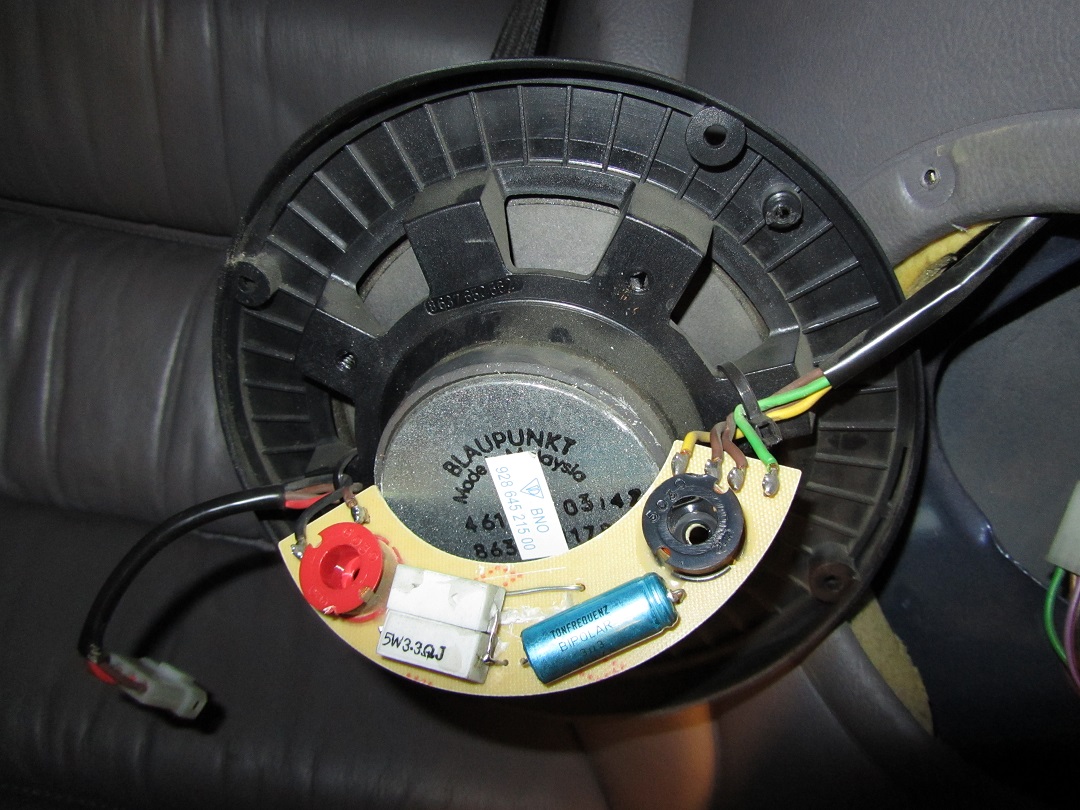
The starting point - about the crossover
Below is a quick diagram of the front crossovers.
The markings are:
R1: RYH4 - 2R2 5% 4W
C1: WEGO ELKO Glatt 23VAC 3.3uF W10 TFZ/TM bi-polar
L1: BLM 9030
L2: BLM 2050
For reference, the measurements of the components are:
High pass:
R1: 2.237ohm
C1: 3.871uF (17% higher than spec)
L2: 202uH
Low pass:
L1: 0.934mH
12-25-2013, 08:42 AM
#3
Nordschleife Master
Thread Starter
At this stage, without more planning, I'm thinking about doing one or more of the following:
1. Replacing old 3.3uF electrolytic cap with newer polypropylene cap of same rating
I'd like to figure out how to make my own meaningful measurements e.g. using a laptop soundcard and mic. so that will come in along the way. Any advice on how to setup relatively easy/cheap recording equipment for measuring frequency/impedance output of audio stuff would be appreciated too!
1. Replacing old 3.3uF electrolytic cap with newer polypropylene cap of same rating
The old cap is electrolytic, and measures 3.8uF capacitance, which is about 15% outside spec. Plus, electrolytic capacitor performance drops off as frequency goes up.
Newer polypro caps (e.g. Parts Express' Dayton audio 3.3uF) will perform closer to target at all frequencies. This is aside from the discussions I've seen about polypropylene caps inherently sounding better (which I'm aware could be a result of internet groupthink).
2. Swapping the inductors between the high and low pass filtersNewer polypro caps (e.g. Parts Express' Dayton audio 3.3uF) will perform closer to target at all frequencies. This is aside from the discussions I've seen about polypropylene caps inherently sounding better (which I'm aware could be a result of internet groupthink).
The low-pass filter uses a single inductor reading 0.9mH, and the high-pass one reads 0.2mH. From my quick experimentation in simulation software, swapping the inductors between each filter this will remove a large dip in SPL around 3200Hz by flattening the crossover's response curve - at the expense of some drop-off in SPL around 15kHz+.
3. Possibly switching to better modern inductors with lower resistanceThe stock inductors are showing high resistance.. 0.9mH reads 13Ohms, and 0.2mH reads 2.8ohms - this is pretty much an order of magnitude higher than most modern inductors used in audio as far as I can gather. Swapping these for something modern with resistances in the 1ohm or lower range should improve things.
4. Maybe replacing the stock crossover completely with something that has a more robust design (e.g. two 12db order filters)Lots of work, including using bread-board to knock up the circuits.
Item 1 above seems to be pretty much a no-brainer based on quick forum reading, and at $2 per cap, a cheap option. The rest of the ideas need further research and more importantly, measurement of the stock driver performance, hence the question in post 1.I'd like to figure out how to make my own meaningful measurements e.g. using a laptop soundcard and mic. so that will come in along the way. Any advice on how to setup relatively easy/cheap recording equipment for measuring frequency/impedance output of audio stuff would be appreciated too!
12-25-2013, 10:09 AM
#4
Rennlist Member
Hi Hilton,
Have a read on the following interesting related tip, especially the information towards the end regarding the rears and it's factory installed - and wrongly wired up - cross-overs: http://www.nichols.nu/tip512.htm
It turned out that this was also wired up in this default wrong way on my own car, which is a MY 1994 (I therefore wonder if it has been wired up wrong in all cars). I modified it as per that tip by wiring it up correctly, and then taking out the 6.6 ohm resistor and putting that in parallel with the 3.3 ohm one (making it therefore 2.2 ohm) and putting a wire instead of the 6 ohm resistor. This all helped sound improvement wise for the rear.
During 2012 I did changed to Hans superb sounding front speakers & passive cross-overs solution and disconnected the rear's, as per my post #285 here: https://rennlist.com/forums/928-foru...uction-19.html I'm very happy with that setup ever since.
By the way: have a look at GoldWave software http://www.goldwave.com/ , now on V5.70 and free to download and try. This has been around for 20+ years, and not bad at all for doing basic digital audio recordings + analysis & manipulation...No affiliation, as always, just passing on what works for me.
Last edited by Arnoud; 12-25-2013 at 01:27 PM. Reason: Added links and a bit more info + pics.
12-25-2013, 05:03 PM
#5
Nordschleife Master
Thread Starter
Hi Hilton,
Have a read on the following interesting related tip, especially the information towards the end regarding the rears and it's factory installed - and wrongly wired up - cross-overs: http://www.nichols.nu/tip512.htm
It turned out that this was also wired up in this default wrong way on my own car, which is a MY 1994
By the way: have a look at GoldWave software
https://rennlist.com/forums/7574000-post9.html
I'll look at goldwave - I haven't scratched the surface yet of what's needed to sort out frequency response and impedance curve measurement, so any recommendations which reduce the internet forum (diyaudio.com mostly so far) and blog reading is welcome
 12-25-2013, 07:24 PM
#6
Nordschleife Master
Thread Starter
http://928s4.com/tips/StereoMods.htm
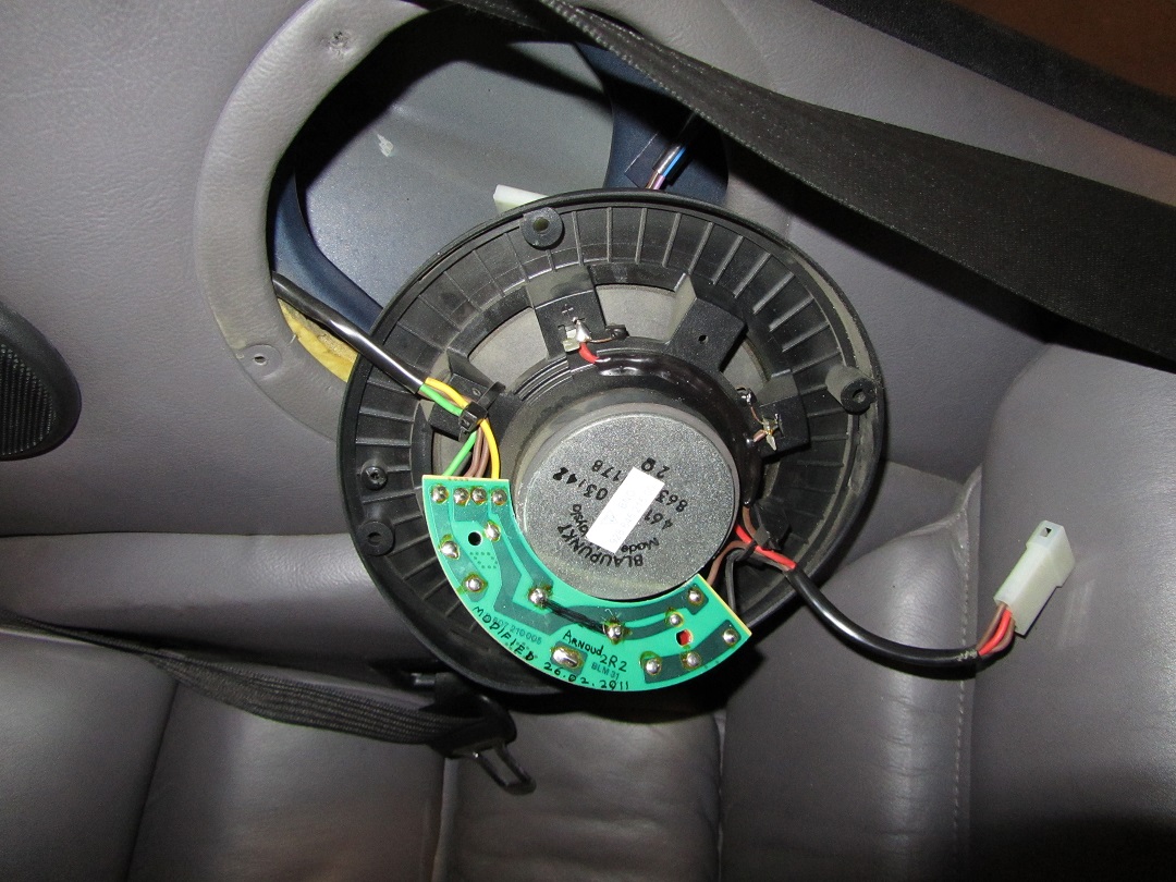
I drew my own version of the rear crossover circuit, so will check it against Chris'
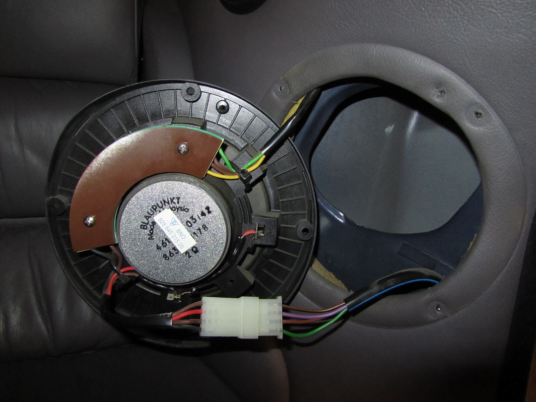
edit: just replaced the pic below - I had the wrong value for a resistor. Now matches what my rears are in my 89. Also interesting - the board for the rear crossovers in my car has hand-drawn traces covered in solder, and a solder-embossed part number. My 89 left the factory in Oct '88 IIRC - I have a letter from Porsche somewhere, so presumably they were still waiting on the circuit boards like Arnoud's pictured above.
edit2: just noticed that the piece screwed on top of the crossover to protect the traces is actually one of the same boards used to make the crossover, with the exact same drillings for pins etc., just without the hand-made traces. Pic added
Last edited by Hilton; 12-25-2013 at 08:05 PM.
12-26-2013, 06:10 AM
#7
Burning Brakes
This insieme real Treasure for me, i haven't never seen those posts And links before, And It is just what i was searching for:updating stock system retaining original parts as much as possible... Thank You,i am starting To update sound system tomorrow.
Francesco from North Italy
Francesco from North Italy
Trending Topics
12-26-2013, 06:38 AM
#8
Rennlist Member
Just checked the source of that nichols tip - it was chris ford, whose site is still up and running including the pics, schematics etc.
http://928s4.com/tips/StereoMods.htm
I drew my own version of the rear crossover circuit, so will check it against Chris'
edit: just replaced the pic below - I had the wrong value for a resistor. Now matches what my rears are in my 89. Also interesting - the board for the rear crossovers in my car has hand-drawn traces covered in solder, and a solder-embossed part number. My 89 left the factory in Oct '88 IIRC - I have a letter from Porsche somewhere, so presumably they were still waiting on the circuit boards like Arnoud's pictured above.
edit2: just noticed that the piece screwed on top of the crossover to protect the traces is actually one of the same boards used to make the crossover, with the exact same drillings for pins etc., just without the hand-made traces. Pic added

For completeness please find hereby the cover protection plate on mine:
 12-26-2013, 08:58 AM
#9
Nordschleife Master
Thread Starter
I just ordered a bunch of capacitors for the first pass.. swapping the stock ones for polypropylene ones.
I ordered 6 of these - http://www.parts-express.com/dayton-...citor--027-420 - I bought extras so I can measure the capacitance and match the left and right sides to each other (I have an old but good Tenma LCR meter)
They won't be here for a couple of weeks.. so I'll find other stuff to do
I ordered 6 of these - http://www.parts-express.com/dayton-...citor--027-420 - I bought extras so I can measure the capacitance and match the left and right sides to each other (I have an old but good Tenma LCR meter)
They won't be here for a couple of weeks.. so I'll find other stuff to do
12-27-2013, 03:35 AM
#10
Burning Brakes
one question, do you think this mods to rear crossover will work also with the 2 aftermarket woofer I bought(4Ohms instead 2 ohms)?or is it unrelated?
Francesco
Francesco
12-27-2013, 04:02 AM
#11
Rennlist Member
More importantly for your question: do you have your 2 aftermarket 4 ohm's woofers connected up to the car factory amp (which you reconditioned with new capacitors etc., IIRC), or to your head-unit and/or other external amplifier?
12-27-2013, 05:40 AM
#13
Nordschleife Master
Thread Starter
The link to another thread I placed in post #5 above is to a post by another user who added another filter in parallel with the rear crossover, so that all three sizes of rear speaker could run off a single channel.
My own intention is to run the woofers on their own amp channel, like the factory setup, with a 150Hz low-pass filter applied. This is because they're 2ohm (my amp can drive 2ohm loads), and I want to adjust the gain on the woofers separately to match the other speakers.
As an aside - I discovered today that the antenna cable from the roof antenna to the head unit had no continuity on the signal pin.
 It was a break in the head unit connector - but I was surprised to find out in the process that the signal wire is hair-thin, so I'm contemplating replacing the whole 4m of antenna cable with RG62 before I put the headliner back in. (RG62 is low-capacitance, 93 ohm cable - better for AM radio reception than more common RG58/59)
12-27-2013, 06:30 AM
It was a break in the head unit connector - but I was surprised to find out in the process that the signal wire is hair-thin, so I'm contemplating replacing the whole 4m of antenna cable with RG62 before I put the headliner back in. (RG62 is low-capacitance, 93 ohm cable - better for AM radio reception than more common RG58/59)
12-27-2013, 06:30 AM
#14
Burning Brakes
Unrelated, as the factory rear crossover's are only connected up to the rear mid-range and rear tweeters (as per the above information and the car electrical schematics).
More importantly for your question: do you have your 2 aftermarket 4 ohm's woofers connected up to the car factory amp (which you reconditioned with new capacitors etc., IIRC), or to your head-unit and/or other external amplifier?
More importantly for your question: do you have your 2 aftermarket 4 ohm's woofers connected up to the car factory amp (which you reconditioned with new capacitors etc., IIRC), or to your head-unit and/or other external amplifier?
Thank you for the informations.didn't noticed the direct wirings from the amp, and forgot about wirings , despite I refoamed old woofers some months ago...
I cut the "useful" part of the old woofers to install new ones(Phonocar 2748) , they are still wired to the original amplifier, amp IC components can lead 2 ohms speakers and can deliver about 28-30w rms , anyway no problem also with 4 ohms(can deliver 23W), I calculate that 2 4-ohms speakers need to be rated for more than 40-45w at least to stand the power output....
I replaced , 6 months ago, every capacitors and every part inside the amplifier, every electronic part that can age ....with good results about sound quality.
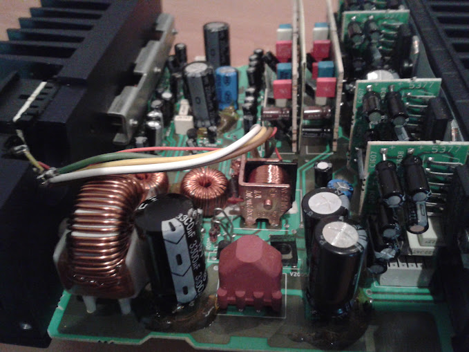
Here you can compare old capacitors dimensions to the new ones(left old, right new ones, hoping that bigger is better):

today afternoon I will investigate and swap green and yellow wires of rear woofer connections.
finger crossed....
Francesco
Francesco