
How to do the boosted car crankcase breathing right
 09-12-2013, 07:58 PM
#16
Nordschleife Master
Thread Starter
Following up on Ake's point about Coyote breather channels:
Here are the inside venting channels visible in the Coyote block. Before this, modular Fords (excluding Ford GT) had all sorts of windage and oil drain problems. According to the Coyote designers, based on magazine articles, these inside breathing channels cured the problems.
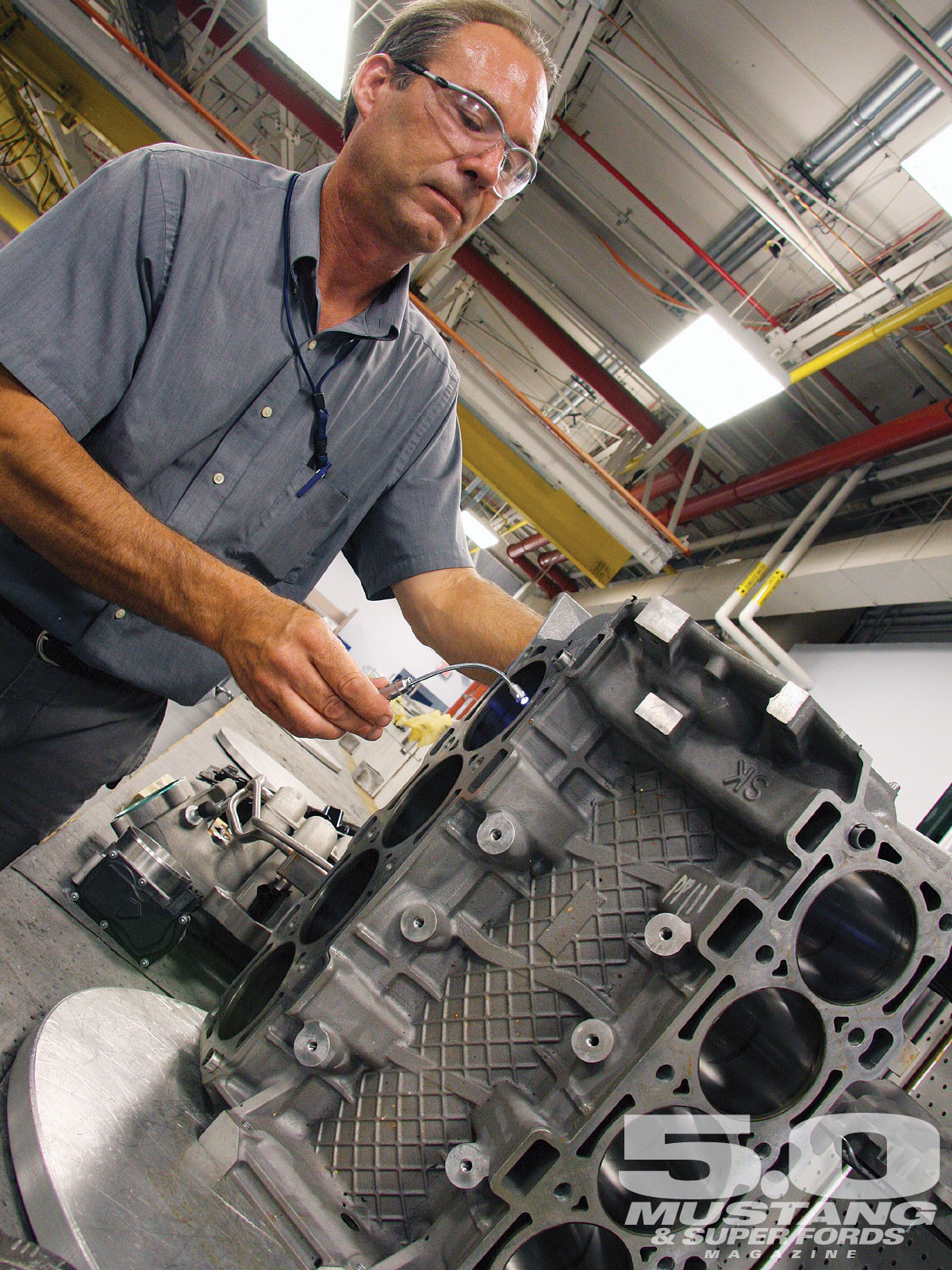
See how big those channels are.
If we could fabricate something like this even just to the end bays, I think a lot of the windage and oil control problems would be solved right away.
Here are the inside venting channels visible in the Coyote block. Before this, modular Fords (excluding Ford GT) had all sorts of windage and oil drain problems. According to the Coyote designers, based on magazine articles, these inside breathing channels cured the problems.
See how big those channels are.
If we could fabricate something like this even just to the end bays, I think a lot of the windage and oil control problems would be solved right away.
 09-12-2013, 11:07 PM
#17
Nordschleife Master
Thread Starter
Yes, that's one option. As long as the pump is reliable and the vacuum is regulated to a relatively modest level, then it's going to reduce all piston pumping problems because of the lower density of the crankcase gas.
09-12-2013, 11:32 PM
#18
Nordschleife Master
This pump has been very reliable, I limit the vacuum by the size of the return line.
I wouldn't run more than 12" Hg in the crankcase without wrist pin oiling mods.
Additionally, those vent channels you show on the block would be very easy to add those channels. The problem is that you could not in any way run the stock intake manifold.
The manifold would have to be similar to what Greg has shown he is making, or better yet a completely new plastic molded intake which incorporated these vents into it.
09-12-2013, 11:58 PM
#19
Archive Gatekeeper
Rennlist Member
Rennlist Member
You might not be able to use rigid channels with the stock intake, but you could tap into the center of the valley and run up to a 5/8" OD rubber hose up and under the fuel rail, then tap somewhere into the valve cover with something bigger than the stock elbows, kinda like so:

09-13-2013, 12:18 AM
#20
Nordschleife Master
Thread Starter
Rob --
In my opinion, the hoses need to be bigger than that to equalize the pulses. I'm thinking >=1" because I want them to flow as well as the oil drainbacks. But basically some port like that. No need for fancy hose ends though, it's just for gas pulses. Weld an aluminum pipe stub to the magnesium valve cover?
Ken's idea about using the cam bearing end cap (or whatever that is) is intriguing. I've seen Nissan Skyline engines that rev to 9000 rpm equalize the pressure pulses from the end like that.
09-13-2013, 12:22 AM
#21
Archive Gatekeeper
Rennlist Member
Rennlist Member
Agreed, the bigger the better. With the stock intake and fuel rails, 5/8 is about as big as you can squeeze under the rails. Perhaps the new intake will allow larger pipes from the chimney and valley floor.
09-14-2013, 09:32 AM
#22
Nordschleife Master
Thread Starter
After thinking about it a bit and looking thru all the simulation data that I have, here's how I think how the gas flow patterns inside the crankcase change over the cycle. Solid big arrows are fast and strong flows, dashed ones are slow and weak:
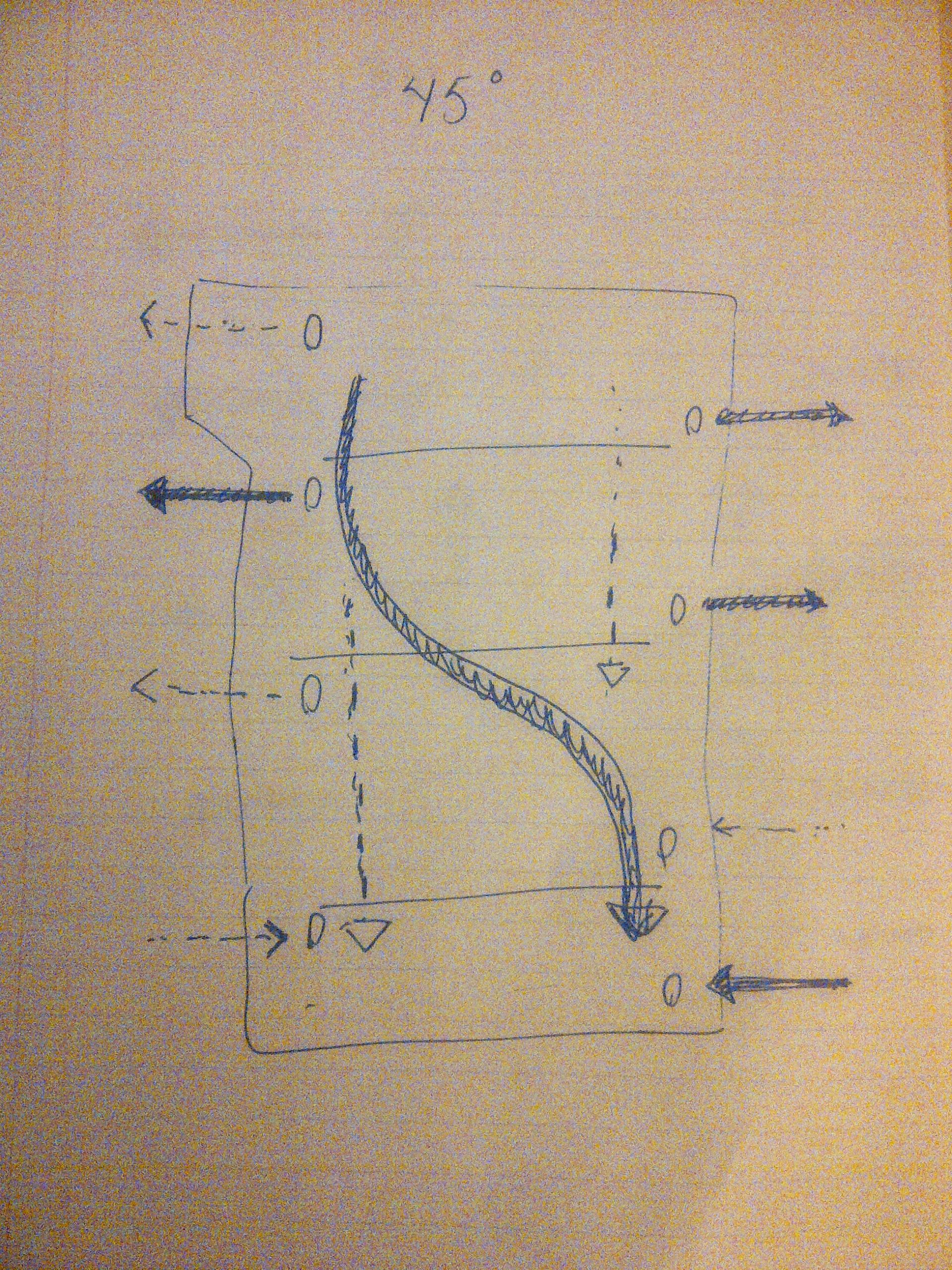
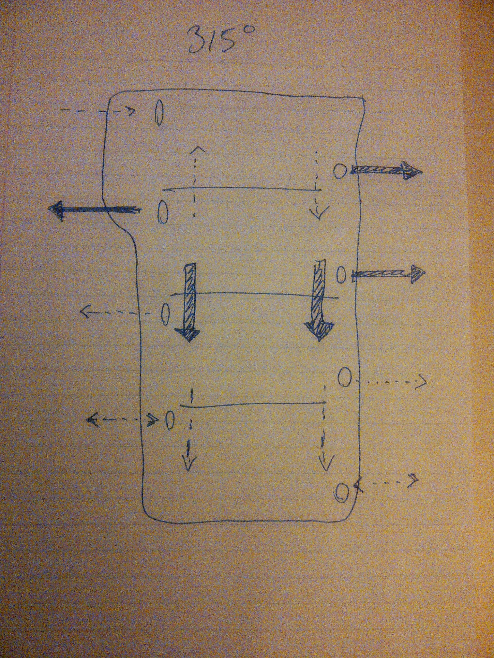
This is for a 6.4L engine that is vented from the valve covers and is running at 6000 rpm.
Some conjectures after drawing those and staring at them for a while:
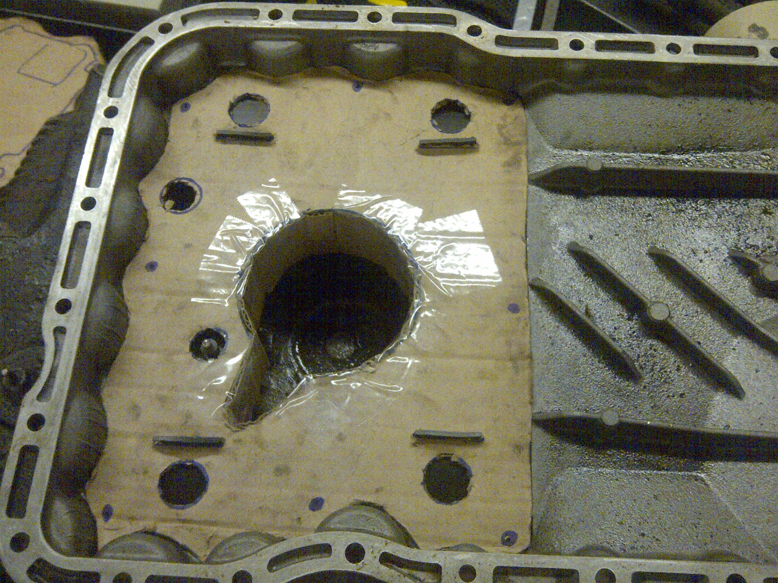
Windage and car accelerations can blow the oil out of the sump, so one needs some sort of sump cover. One-way valves should allow for good baffling in the corners while still allowing drainback. The good news is that the sump covers are relatively easy to test.
An example here. This is similar to Louie Ott's sump cover, except I've added one-way valves:
Other ideas and observations:
The pan spacer is a no-brainer since it increases the crankcase volume and makes all gas movements less extreme.
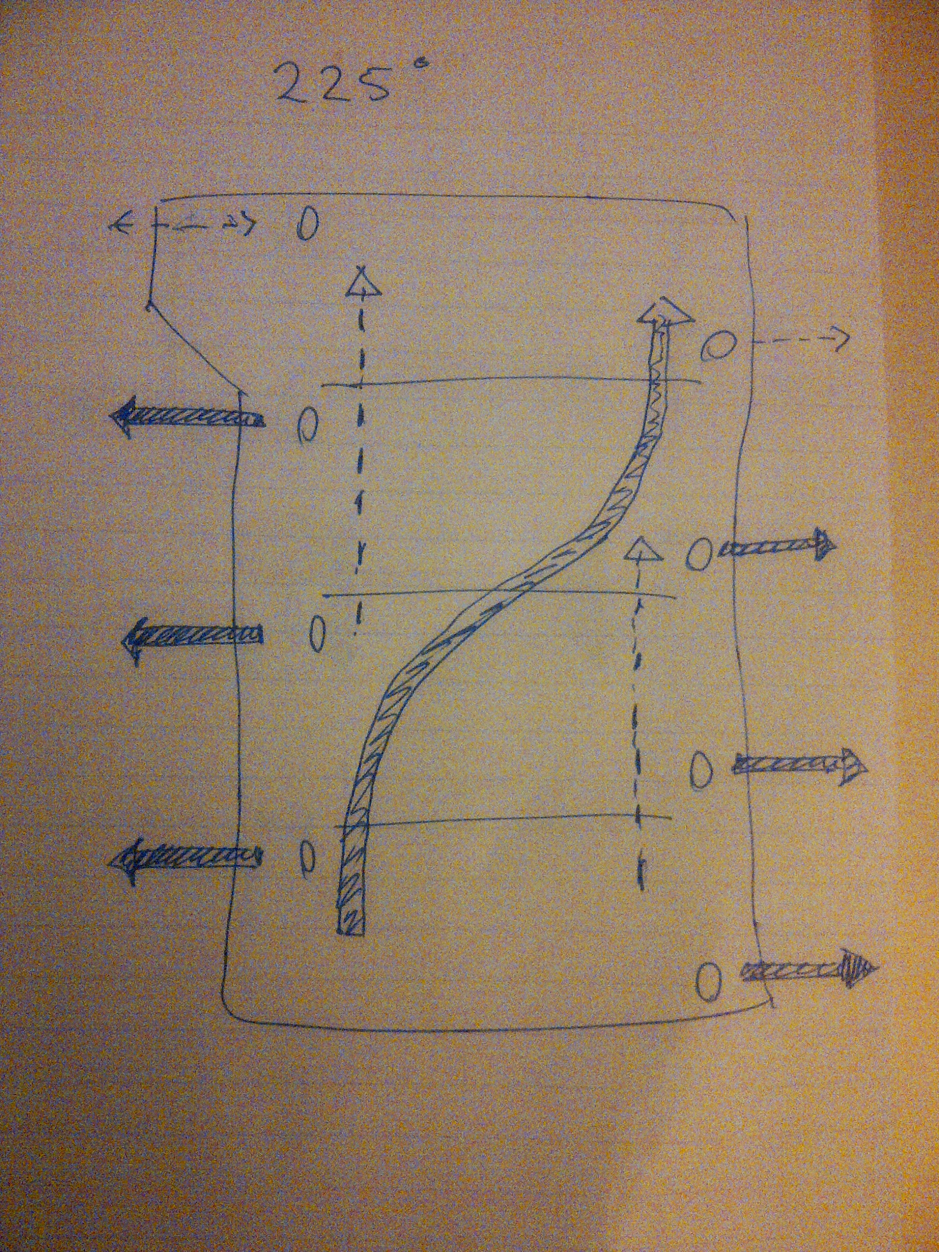
At 45 degrees and 225 degrees of crankshaft, there's a big windage issue inside the crankcase. The pressure differential between the front bay and back bay is the largest at those points. The pressure equalizes partially thru the oil drains, potentially disturbing oil flow down.
One strategy for reducing the 45/225 degree cycling in the front oil drainbacks is connecting the chimney to the front part of the valve cover on both sides. This has been discussed in detail earier in this thread. Now the piston pumping pulse can travel outside the front oil drainbacks. My hope is that this will allow the front oil drains to move less gas up and drain oil down more effectively. The practical consideration is what is the largest diameter hose I can practically use to connect the oil filler neck base and the valve covers. The best place to run in on a stock engine is probably under the water bridge.
On the bottom of the pan, I want to extend the angled fins in the bottom of the oil pan to encourage gas flow from the rear to front, while discouraging gas flow from front to back in the bottom. The reason why the angled fins do this is that the flow goes across the pan over the different diagonal at 45 vs. 225 degrees. The front to back flow at 45 degrees should probably be directed to flow above the crankshaft thru the breather holes in the webs. Here the crankshaft counterweight design is critical (and incidentally this is one of the reasons why the GTS crankshaft sucks hairy *******.) If one manages to do that, then the windage pattern will also help move oil from the middle of the pan towards the front sump.
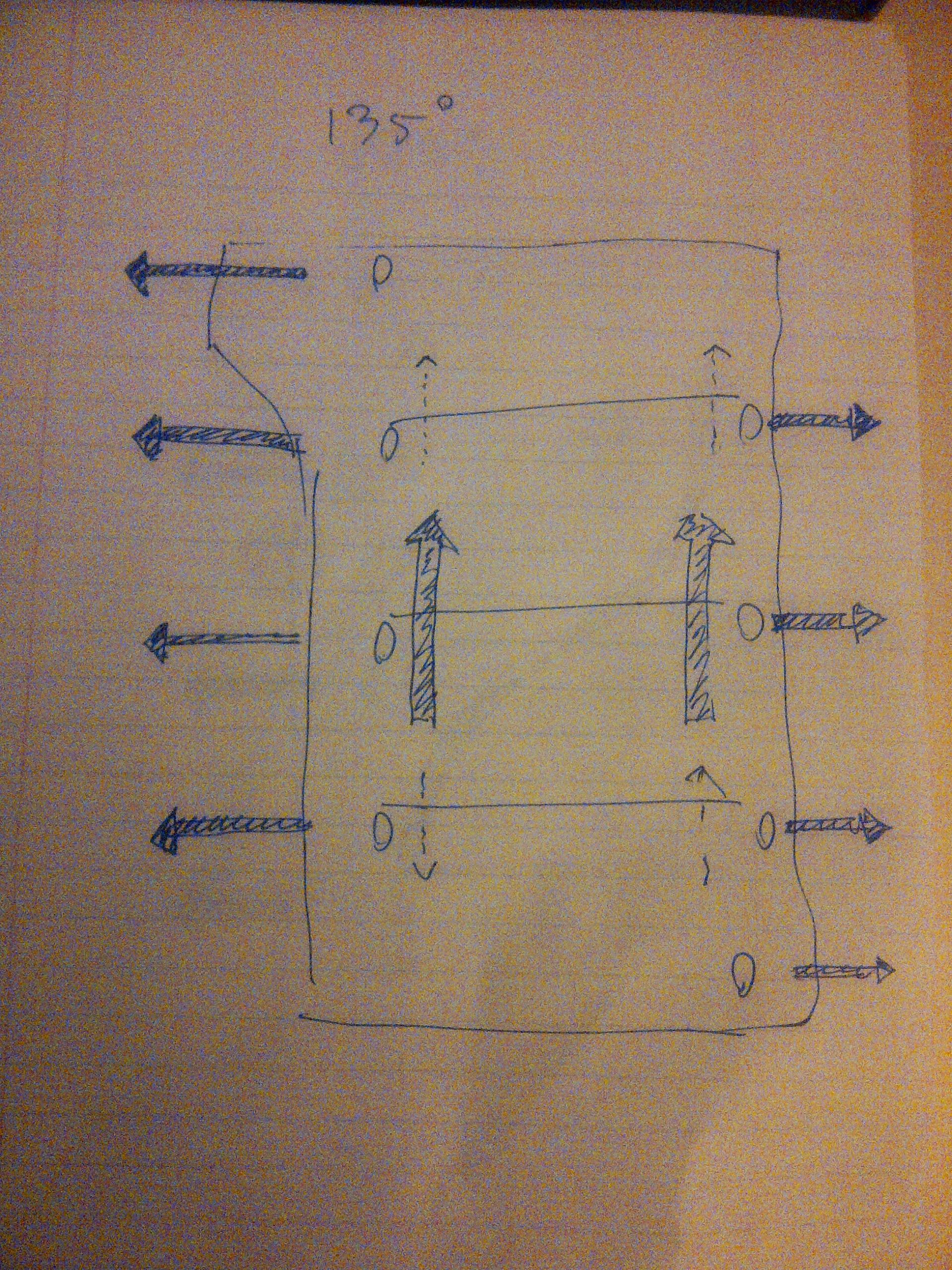
For the 135 and 315 degree flows, one needs breather holes on the center main bearing sides. GTS has those.
All in all, a GTS block with S4/GT crankshaft, sump cover, pan spacer, windage tray with diagonal fins, and chimney connected to the valve covers, should work pretty well in terms of windage gas flow.
This is for a 6.4L engine that is vented from the valve covers and is running at 6000 rpm.
Some conjectures after drawing those and staring at them for a while:
Windage and car accelerations can blow the oil out of the sump, so one needs some sort of sump cover. One-way valves should allow for good baffling in the corners while still allowing drainback. The good news is that the sump covers are relatively easy to test.
An example here. This is similar to Louie Ott's sump cover, except I've added one-way valves:
Other ideas and observations:
The pan spacer is a no-brainer since it increases the crankcase volume and makes all gas movements less extreme.
At 45 degrees and 225 degrees of crankshaft, there's a big windage issue inside the crankcase. The pressure differential between the front bay and back bay is the largest at those points. The pressure equalizes partially thru the oil drains, potentially disturbing oil flow down.
One strategy for reducing the 45/225 degree cycling in the front oil drainbacks is connecting the chimney to the front part of the valve cover on both sides. This has been discussed in detail earier in this thread. Now the piston pumping pulse can travel outside the front oil drainbacks. My hope is that this will allow the front oil drains to move less gas up and drain oil down more effectively. The practical consideration is what is the largest diameter hose I can practically use to connect the oil filler neck base and the valve covers. The best place to run in on a stock engine is probably under the water bridge.
On the bottom of the pan, I want to extend the angled fins in the bottom of the oil pan to encourage gas flow from the rear to front, while discouraging gas flow from front to back in the bottom. The reason why the angled fins do this is that the flow goes across the pan over the different diagonal at 45 vs. 225 degrees. The front to back flow at 45 degrees should probably be directed to flow above the crankshaft thru the breather holes in the webs. Here the crankshaft counterweight design is critical (and incidentally this is one of the reasons why the GTS crankshaft sucks hairy *******.) If one manages to do that, then the windage pattern will also help move oil from the middle of the pan towards the front sump.
For the 135 and 315 degree flows, one needs breather holes on the center main bearing sides. GTS has those.
All in all, a GTS block with S4/GT crankshaft, sump cover, pan spacer, windage tray with diagonal fins, and chimney connected to the valve covers, should work pretty well in terms of windage gas flow.
09-14-2013, 01:03 PM
#23
Rennlist Member
Join Date: Feb 2011
Location: Mostly in my workshop located in Sweden.
Posts: 2,230
Received 463 Likes
on
248 Posts
If anyone like to acquire the one-way rubber valves mentioned by Tuomo and partly shown in the picture of the paperboard mockup baffle, the valves are available as BMW M3 E30 spares, part number 11 13 1 309 428. Pictures showing rubber flaps and baffle walls.
Ake
Ake
Last edited by Strosek Ultra; 10-31-2013 at 09:44 AM.
09-14-2013, 07:16 PM
#24
Rennlist Member
Colin, this sounds like your oil/air separator is after the pump, so it is pulling oily air through the vacuum pump, is doesn't sound right. Can you clarify?
Then you also have the option of a vacuumed crankcase too......
The way I run my system is as follows.
I run a VP102 GZ motorsports vacuum pump in place of where the stock air pump normally sat.
This pulls from the chimney via a 3/4" line (all that is needed with this vacuum pump).
From here it goes through the pump and into a custom air oil seperator which is of centrifugal design.
The free air vent on here could be returned to the stock intake suction, which would help to increase pump efficiency at higher RPMs. On a boosted car it would need to be sucked in before the turbo/SC inlet.
The oil which is seperated out by the pump/seperator would be then trapped in the bottom of the seperator. Instead though, I have a -3 hose which connects the bottom of the seperator to the 1-4 bank valve cover. The vacuum from the pump pulls the oil back into through the valve cover which then creates a natural flow of gasses (and oil) back down into the block. The benefit of this is that when the cars are being driven with high cornering (g) forces the oil will have a significantly reduced (if not prevented) ability from travelling up the 1-4 bank head drains. This then in turn leaves more oil in the sump for better oil control.
Since doing this the oil consumption of the engine disappeared entirely. I did notice a small increase in power from doing this as well due to the aided sealing of the rings which the vacuum provides.
12-10-2013, 11:10 AM
#26
Electron Wrangler
Lifetime Rennlist
Member
Lifetime Rennlist
Member
Actually a little oil mist is required for the vacuum pump lubrication with this pump - so assuming the AOS does its job well - sucking through the AOS is not an option.
Pumps not designed for this use might have issues with heavily laden oil mist ingestions - but not here.
e.g. the stock emission air pump would not like this - but it wouldn't pull much vacuum either so would be almost pointless in this application.
Alan
Pumps not designed for this use might have issues with heavily laden oil mist ingestions - but not here.
e.g. the stock emission air pump would not like this - but it wouldn't pull much vacuum either so would be almost pointless in this application.
Alan
12-10-2013, 03:51 PM
#27
Rennlist Member

I've found this discussion (and the provent thread) interesting. Mostly over my head, but interesting. How big a problem is this for a stock S4 motor?
12-10-2013, 06:29 PM
#28
Three Wheelin'

Interesting that Ford did that style ventilation system with the new coyote engine recently. Honda has been doing this for years! Look at their NSX v6 engines or their 4 cylinder engines. Very interesting.
If you use the 2 valley ports on a 928 to vent out the block, what would you do about the knock sensors?
If you use the 2 valley ports on a 928 to vent out the block, what would you do about the knock sensors?
12-10-2013, 06:38 PM
#29
Supercharged
Rennlist Member
Rennlist Member
Join Date: May 2002
Location: Back in Michigan - Full time!
Posts: 18,925
Likes: 0
Received 60 Likes
on
34 Posts
So in my case, it's a BIG deal (now you know why I'm always piping in). For the 99% of owners, they might be able to live with it just the way it is... okay not the GTS crowd, but the rest for sure. It's a weak point for sure on these really great engines, but it's not an engine killer for daily driving.
I think we are getting close to fixing the issue at a reasonable cost. So far, my solution seems to work pretty well on the 16v engine, but the jury is still out. I'm going to re-design and modify it slightly for the 32v this winter.
12-11-2013, 06:07 AM
#30

Ptuomov said "The pan spacer is a no-brainer since it increases the crankcase volume and makes all gas movements less extreme". Connecting the front and the rear of the crankcase to help equalise pressure has also been suggested.
Combining these two concepts: large volume external connector between front and rear of crankcase (above oil level), with intermediate passive air canister. This would further increase effective crankcase air volume (hoses and canister combined) and the passive canister would also serve to 'borrow' from when under vacuum from one end of engine and to 'lend' to when under pressure from the other end of the engine, thus reducing internal crankcase air movement and internal fore / aft pressure differentials. Fine in theory - where to put such a device? Inner guard?
Combining these two concepts: large volume external connector between front and rear of crankcase (above oil level), with intermediate passive air canister. This would further increase effective crankcase air volume (hoses and canister combined) and the passive canister would also serve to 'borrow' from when under vacuum from one end of engine and to 'lend' to when under pressure from the other end of the engine, thus reducing internal crankcase air movement and internal fore / aft pressure differentials. Fine in theory - where to put such a device? Inner guard?